Scaling Analog Inputs to PowerFlex 525
7/1/22 | Scott Savage, Rexel Technical Consultant

7/1/22 | Scott Savage, Rexel Technical Consultant
This post addresses analog scaling to the analog input to the PowerFlex 525 drive. The example is a 4-20mA signal with a different minimum or maximum frequency output from the drive. Since 0-10VDC is easy math, we will just discuss 4-20mA signals and how they affect the span of the drive frequency if changed to something different than 0-60hz.
Please keep in mind that PowerFlex 525 drives are only speed regulators, and all references will be regarding engineering values of hz.
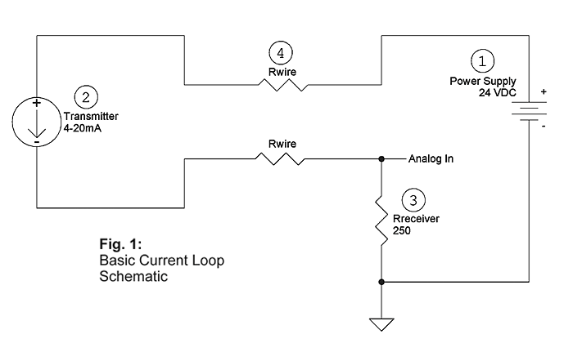
Below is a typical 4-20mA from a transmitter. It could be from a PLC or another source providing the speed reference to the PowerFlex 525 drive.

The PowerFlex 525 is limited on trimming the incoming signal from the analog output from the device. The analog value is directly tied to the frequency span of the drive, which is determined by minimum (Par P043) and maximum (Par 044) frequency settings.
The only way to adjust is by scaling the analog input of the drive from the source. Let’s take an example of 50% speed on the span you need to achieve 30 hz.
Feel free to adjust the analog output from your device to reach this desired speed to make sure the span is correct from the device commanding the speed of the drive.
How Do You Know What the Analog Value Should Be?
Fill in the tangerine data cells in the spreadsheet for either 0-10V or 4-20mA signal, the value in volts or milliamps will appear in the green field. This will significantly save time on spot calculations and will scale the analog signal to the correct speed.
Good luck with your installation!
Need a hand dialing in the correct speed? Contact us today!