
Blog > Automation > Energy Savings Using VFDs: Just the Facts
Energy Savings Using VFDs: Just the Facts
6/1/22 | Scott Savage, Rexel Technical Consultant
Blog > Automation > Energy Savings Using VFDs: Just the Facts
6/1/22 | Scott Savage, Rexel Technical Consultant
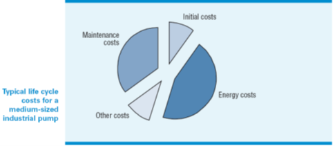
Did you know that electrical motors consume about 60% of all electrical energy that is produced today? Almost half of that power is used to drive variable-torque loads such as fans, blowers and pumps. Energy use makes up almost half of the total life cycle cost of a medium-sized industrial pump. That means there are multiple energy savings opportunities that exist with air compressors, fans, and pumps in your facility.
Dampers on fans and throttling valves on pumps create pressure differential and lower the efficiency of the system. Air compressors already low in efficiency can be folded back in voltage to conserve energy also.
Centrifugal pumps and fans are a good target to choose for energy savings. Dampers (fans) and valves (pumps) would be opened, and the VFD will determine the flow with some sort of a feedback device such as a pressure or flow transducer.
A setpoint in the controller (PLC for example) will have a certain PSI (pressure) or GPM (flow) demand for the process. Feedback from the process transducer is sent to the controller. The loop calculates the error between commanded setpoint (desired process unit) and transducer feedback (what the process is operating at). The controller increases or decreases speed of the VFD so the feedback is the same value as the setpoint. The VFD modulates to hold this setpoint.
PID loops in the controller (Allen-Bradley®) have three components:
- Proportional – Evaluates error between setpoint and feedback and reacts in either positive or negative output response to the VFD
- Integral – Time slice to evaluate changes to setpoint and feedback
- Derivative – Not used with VFD control
Gains can be programmed in the PID loop to affect the reaction time.
Proportional – higher the gain makes the loop to the VFD react faster
Integral – higher the gain makes the loop to the VFD react slower
Let us take a look at the pressure required to overcome an elevation change.
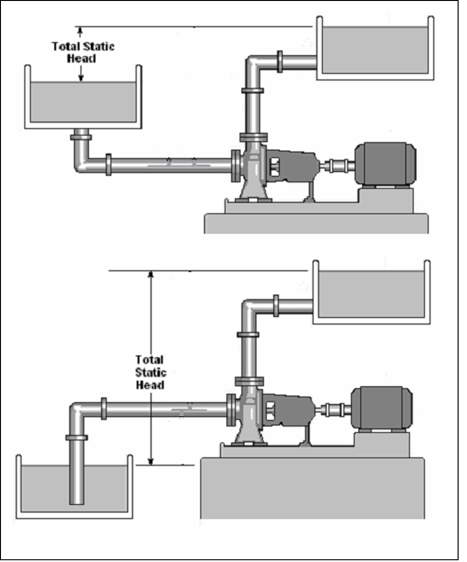
Head in feet = (Pressure in p.s.i. ×2.31) / Specific Gravity
Total Head = Static Head (head in feet) + Dynamic Head (pressure due bends, valves or dampers, etc.)
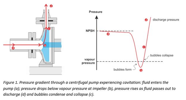
Please consider the NPSH (net positive suction head) of the pump, it may prohibit you from slowing the pump motor down to required process with a VFD. Understand the NPSH and the pressure on the outlet side of the pump. High head applications on outlet side of pump or poor NPSH on the pump are usually not a good application for energy savings on VFDs.
Pumps may overheat if not supplied with sufficient inlet supply, cavitation damages pumps, make sure you stay in acceptable ranges in speed. Please keep in mind, the energy savings are in the higher speed ranges of your pump/fan curve, not in the lower ranges.
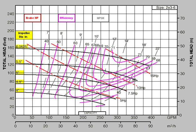
In review – pump curve shown above
5.5” impeller 175 GPM@ 118 FT total head requires 7.5 BHP (brake horsepower) and is 63% efficient.
To understand the pump performance and its efficiency, you need the pump curve for crucial information. Be careful not to fall too far off the pump/fan curve (efficiency) as the drive folds back the speed of the motor (change in frequency). The GPM decrease may put you too far to the left of the pump/fan curve.
5.5” impeller 125 GPM@ 118 FT total head still requires 7.5 BHP (brake horsepower) and is 55% efficient.
The pump curve shows the efficiency of the pump not the motor efficiency. Please keep in mind any increase in efficiency of the motor or pump puts more money in your pocket.
Premium efficiency motors decrease apparent power (what you pay for from the utility) to the pump/fan, with less iron and copper losses.
The higher the pump efficiency and motor efficiency the greater the return on investment.
Understanding the characteristics of the pump helps determine good decision-making that leads to better results. Contact the pump manufacturer or distributor or go online for this information for best results.
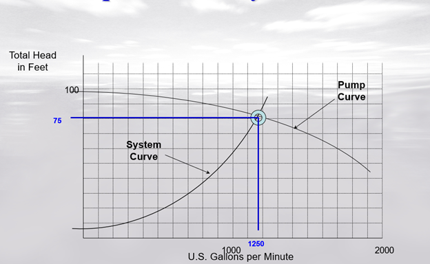
The pump will run at base speed of the motor (60Hz) for the pump curve and will intersect with the system curve to provide the flow and pressure at full speed.
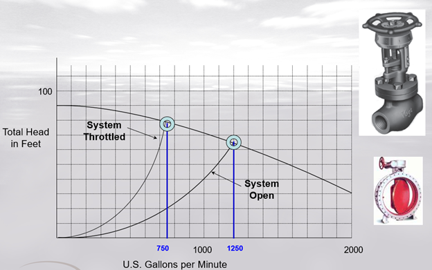
Throttling with a valve shifts the system curve, increases the pressure and decreases flow. Losses occur as the total head increases.
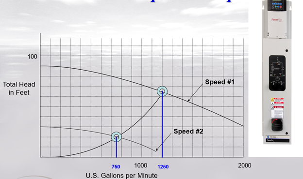
Changing speed with a VFD changes the pump curve instead of throttling and changing the system curve. Notice the pressure in total feet decreases instead of increasing by throttling.
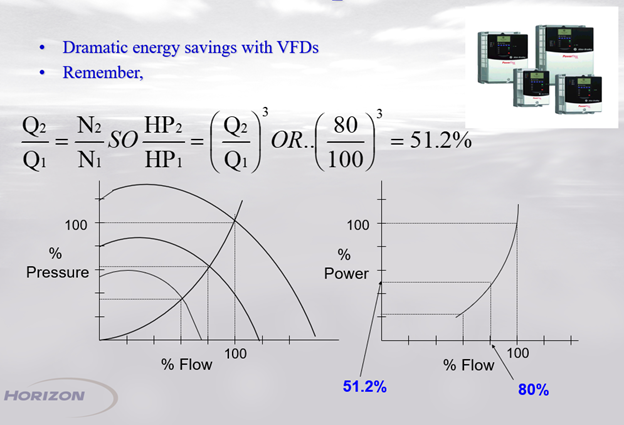
Since pump speed N2 (with VFD) is less than N1 at base speed of the motor running across the line (frequency 60hz), the ratio will be under a value of 1 for N2/N1. Pump speed now determines the flow when unrestricted by a valve. This ratio determines the energy savings.
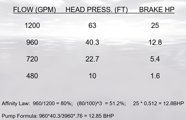
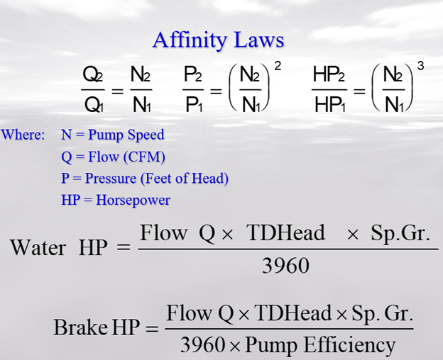
Please keep in mind that the example shown above is at full brake HP, this may be different than the application you may have. Shown above in an ideal situation, the BHP required at 80% speed is almost a 50% savings. Observe the Affinity Law calculation the ratio of speed is cubed to achieve a percent of existing HP. The 25HP motor now has a 12.85 brake horsepower needed to run the process.
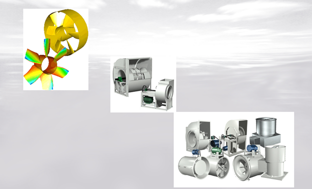
Axial Fans – top left example flow parallel to axle of fan
Radial – middle example air flows perpendicular to the axle of fan
Centrifugal Fan – bottom right air flow through axle side and discharged due to higher pressure demands, they have various impellers depending on gases or material running through the ducts.
The different types of centrifugal fans:
- Forward curved centrifugal fans.
- Backward curved centrifugal fans.
- Crossflow / tangential fans.
- Radial bladed fans.
Centrifugal fans operate well in high-pressure industrial applications.
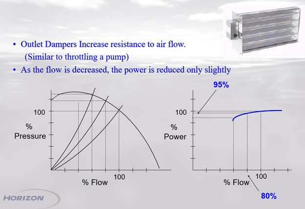
Dampers change air flow for the process but use close to the same amount of power used at full speed. Look for these energy wasters in your facility and place a VFD on the fan or multiple fans with one drive.
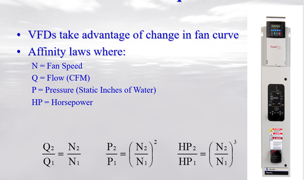
Same affinity laws apply to fans just like the pumps. Please take note the pressure ratio is the square of the speed if you have these values and want to calculate.
Please keep in mind the example is for an ideal situation with a fan motor running at full brake horsepower and damper control. A VFD will fold the voltage back and torque (less pressure) will attenuate with reduced speed.
Torque = V/hz
Running in a V/hz mode with the VFD and opening restrictions that create differential losses optimizes the affinity law to save significant energy we all use.
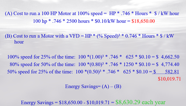
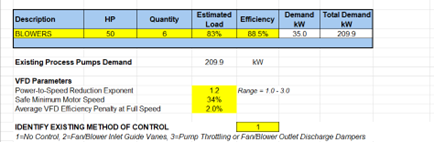
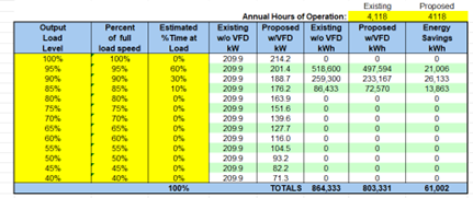
Know your electric rate in $/kW*hr and estimate your usage in % speed and how long you run at those different speeds for a rough calculation by hand. You might be pleasantly surprised.
ESCO stands for Energy Service Company. The term Energy Savings Company is also used. It is a company or an entity that delivers energy services or other energy efficiency improvements in an energy user's premises, and accepts some degree of financial risk in doing so.
The ESCO can provide funding to projects and help make it more economically feasible to proceed with a project that consumes power. This reduces utility energy usage; avoids the construction of new power plants. A win for all.
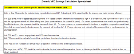
Your ESCO will provide you with a calculator (this will determine your energy savings). Pump curves and electric bills will be required information upon submittal of your application. The general rule is the ESCO might pay the difference to achieve a 2-year payback on your project. Most companies will approve the cost of a two-year payback on their investment for capital projects. If the project payback is less than 2-years, you should probably do the project on your own.
Please consult your ESCO engineer for the proper Power-to-Speed Reduction Component for proper results with the calculator.
Rexel Energy Services can assist with the submittal to your ESCO and expedite the process along your savings journey. Please feel free to contact us for details.