
Blog > Automation > 5 Best Practices for Drive Enclosures
5 Best Practices for Drive Enclosures
8/8/19 | Will Cole, Rexel Technical Consultant
Blog > Automation > 5 Best Practices for Drive Enclosures
8/8/19 | Will Cole, Rexel Technical Consultant
These best practices for drive enclosures will save you time—and frustration. Drives are often used and specified for use in industrial applications. From conveyors to pumps, drives are an efficient piece of automation technology. This blog post will walk through a PowerFlex® 525 AC drive real-life example.
This post will scratch the surface of the guidelines, best practices, and math used to take a known drive and find a suitable enclosure (aka box) to put that drive into. Our post will walk through five steps:
Will your drive fit in the enclosure? In a very basic sense, most drives are three-dimensional boxes (a cube). They have a width, a height, and a depth. In reality, drives also have curves, notches, and other geometric abnormalities to their profiles, i.e., they’re not a perfect cube. But for the purposes of discussion, we take the largest value for any one dimension and use that as our parameter. This step means: verify the width, height, and depth of your drive and then select an enclosure that will—at a minimum— encase that object. Example:
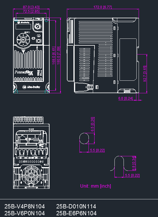
© Rockwell Automation®
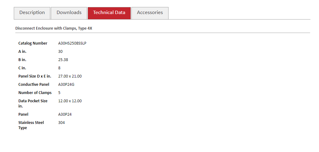
The A30HS2508SSLP is a disconnect enclosure, and its approximate size is 30” high x 25.38” wide x 8” deep. We compare the width, height, and depth of your drive versus the corresponding dimension of the enclosure. All three dimensions fit, so we can move on to step two.
A30HS2508SSLP HOFFMAN Enclosure Dimensions
If we tried to put this drive into a Hoffman CSD12106, it wouldn’t work. That enclosure is wide enough and tall enough, but the depth is a mismatch. Depth of 6.77” (drive) versus a depth of 6.00” (enclosure). Plus, the drive would mount to a back panel, which adds approximately 0.125”. The back panel stands off the actual mounting backplane of the enclosure about another 0.5”. Rule of Thumb: Typically, we assume 0.75” of depth when using a back panel within a standard enclosure. Assume 6.77” + 0.75” = 7.52”. You might be able to fit drive 25BD010N114 into a CSD16128 (changing to 8” of depth), but you might not want to, which brings us to the next best practice for drive enclosures.
This step has to do with the actual square footage footprint, namely width and depth on the backplane of your control panel. Just because you can fit the drive into a box, doesn’t mean you should cram it in there—CAN doesn’t mean you SHOULD. Most drive manufacturers will publish guidelines about how much space (in inches) to leave between drives and/or under each drive, or even in front of each drive. These clearances can be found online for most Rockwell Automation® drives. Our previous example had selected drive 25BD010N114. Now, let’s say we want to put two of that same drive into an enclosure. Some folks might call this “ganging up,” and it is not uncommon to see six or ten or more drives all ganged up into one enclosure. For this, we want to review the minimum mounting clearances. In this case, a 270+ page user manual document exists covering these questions. Click here, skip ahead to chapter one, page 15.
© Rockwell Automation
We have two drives. The work is already done for you! These diagrams show many ways to mount your drive or drives. Vertical, zero stack, with fan kits, sideways (horizontal). Each diagram includes suggested dimensions. In this case, almost always 2” on the top and 2” on the bottom of each drive. If you build electrical panels, these diagrams should make sense to you. They show where the wiring and/or duct would be. Our expanded example is for two 25BD010N114 drives, and we’re mounting them vertically. That means side by side with 1” between them. That gives us a special footprint of (W+W+1) x (2 + H + 2) or calculated out to (3.43” + 3.43” + 1 = 7.86”) x (2” + 7.09” + 2” = 11.09”).
That will all still fit into enclosure A30HS2508SSLP. On to step three.
In addition to the called out physical dimension of depth, there are also a couple of considerations for the overall depth of the installed system. Namely, there may be a consideration for depth to let the drive breathe or to account for cables that connect via the front face of the drive. This is more commonly seen in servo drives. Our two 25BD010N114 drives do not require additional mounting depth considerations. But, to take an example, consider servo drive 2097-V33PR5. This is a totally different type of automation product than the aforementioned 25BD010N114 drive, but they are both called “drives” by some users. So, let’s just take a quick look.
This is a good example for the world of servo drives. Returning to earlier example, the two PowerFlex 25BD010N114 drives that we put into enclosure A30HS2508SSLP. There are no additional requirements for our selected drive(s) at this step.
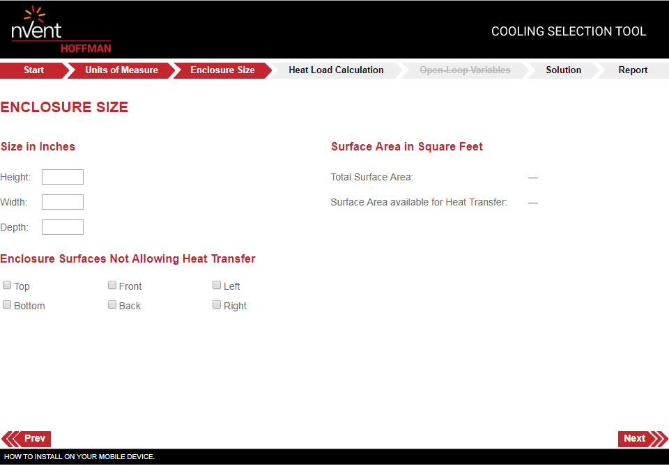
If you’ve made it this far, you have a good mechanical fit. Your drive should fit in your enclosure, and you should be able to make all connections and still close the door. But it’s important to know that drives create heat. In general, too much heat inside an enclosure runs a very serious risk of damaging key electrical and electronic components like circuit boards. This step delves into electrical heat load. We approach this step by finding two bits of information:
Those two pieces of information can be found in the user manual for the drive. Then, we need to use about ten more known technical inputs to run this build through a calculator. The other information includes the width x height x depth of enclosure (for a contained cubic volume), ambient temperature, and more. We can also provide input as to whether we have fans on each drive, which is a commonly added option. We can also provide input as to whether we have a fan or an AC unit on the enclosure itself, or even an air exchanger or heat exchanger. These calculations involve BTU (thermal unit of measurement) and CFM (cubic feet per minute). You can get started here.
Honestly, we don’t have enough time or space on this blog to explain ALL those calculations. To keep step four simple, we’ll check:
Step four can get quite complex and involve other considerations. For example, some folks might assume that 10% of the energy is dissipated as heat. Some might not. Your applications are unique. We can work with the manufacturer to help you with these calculations on your next project.
I know, just everything else. For a large and complex control panel, this step could be a 50-hour project in and of itself. Each item in your system has the capability of generating heat, and each item in your system has three dimensions of space to consider. Even a terminal block takes up width, using a bit of available DIN rail real estate. New, unplanned, and unexpected components sometimes have depths you haven’t yet factored. If the depth of a network switch prevents you from closing the door to your enclosure, that is a very bad thing. What about where your finished control panel is going? Inside? Outside? We didn’t have space above to delve into enclosure type or a required NEMA rating. Those are two very important topics to discuss. Meaning, if you have an electrical enclosure in a space on a factory floor that gets washed down with water and/or cleaning chemicals, you’ll very likely need to explore options like NEMA 4X and stainless-steel enclosures.

These best practices for drive enclosures take on the relatively small scope of putting one or two drives into an enclosure. Your systems may be quite complex and interrelated, so the maxim of “check everything else” isn’t meant to be covered by this post. This post was intended to introduce the guidelines, best practices, and math used to take a known drive and find a suitable enclosure to put that drive into. Our team of specialists can help you navigate all the factors. Contact us today!