
Blog > Automation > Basic Rules for Dynamic Braking Resistors
Basic Rules for Dynamic Braking Resistors
3/10/20 | Scott Savage, Rexel Technical Consultant
The Advent of VFDs and Dynamic Braking
Since the first industrial revolution (1760-1840), manufacturers have needed to start and stop loads of various sizes. Loads rarely stay at a constant speed, and they don’t stay at rest for long periods. In this present fourth industrial revolution and with the advent of smart manufacturing, variable frequency drives (VFDs) enhance the process in most manufacturing applications. Cycle time is much shorter, and braking needs to be less mechanical and more electronic. Dynamic braking with VFDs allows long life without mechanical wear on the braking system. In fact, it is very economical, and no downtime maintenance is required.
Don’t Run Off the Rails
You may ask, what is a dynamic brake and how much cost is involved in creating an electronic braking system for a drive? Before we answer that question directly, let’s first look at why dynamic braking is necessary with a hypothetical scenario.
Your brand-new drive is faulting on bus overvoltage. How could this happen? The drive should surely handle the load, slowing it down as it did to accelerate the motor - correct? The fact is, we are on a one-way street; power can come into the drive utilizing a six pulse drive, but not exit the drive back through the rectifier (bridge) to the power distribution.
There are two types of AC drives, six pulse drives, and regenerative types of drives (755TR and 755TM). The six pulse drive allows an electrical current to travel to the motor. What happens, though, when all the energy stored in the mechanics of the process needs to stop?
A great example is a roller coaster running on a drive system at the theme park. When you have a six pulse drive, and you’re decelerating a motor rapidly, and it becomes a generator, the drive can’t place the excess amount of energy back on the power distribution system. The bridge (rectifier) only flows toward the DC bus and not in reverse toward the electrical source that supplies the drive. The DC bus of the drive reaches full capacity (capacitor voltage rising), and the load keeps sending more power to the DC bus (storage using capacitors). The motor is now generating power back to the drive with strong deceleration. Two things are required at this point, more negative motor torque and somewhere for the watts of power to be dissipated.
No worries! Braking Resistors to the Rescue
So many questions to answer, right? Probably not as many as you think, though. Everyone wants an easy answer. It’s either electrical or mechanical, right? The fact is, it’s both. It’s time to put our thinking caps on to resolve the Bus OverVoltage Fault situation.
You may not be an engineer who would mathematically solve the issue with complicated braking equations or software. You just want to stop all the nuisance that’s tripping off the drive. You also are trying to get the right size resistor for your application quickly. Well, there are actions to take to make a solid decision on an AC drive resistor choice. Braking resistors are inexpensive and easy to install. It is a simple DC circuit V=IR.
The Chemistry of Successful Braking Resistors
Braking resistors have two properties, and both are very important to the success of the smooth deceleration of the VFD without any interruption of drive faults:
- Resistance in Ohms (Negative Braking Torque)
- Wattage (Duty Cycle)
Buying the largest resistor is not the answer. No one wants to purchase a boat anchor when they buy a resistor. So, let’s review what these features are and how they work.
Let’s start with the Ohm value for the brake. Remember the V=IR equation? Well, if the R (Ohms) component is too low for a certain V (voltage), that means I (current) is going to increase at that voltage level. If the current is too high, the braking transistor (sometimes called a chopper) will fail due to excessive current running through the circuit.
Rockwell Automation® drives have an installation manual that is separate from the programming manual that defines a minimum Ohm value for that 7th insulated-gate bipolar transistor (IGBT) or chopper. You must stay above the minimum value, or the chopper will fail. The 7th IGBT only switches on when the DC bus voltage of the drive rises and triggers the resistor into the circuit (for example, the DC bus voltage at 480VAC input is 650 VDC, the chopper will turn on above 750 DC to avoid tripping (fault)).
The Math of Successful Braking Resistors
Why is this important? The lower the resistance, the higher the current in the braking circuit and the greater the negative motor torque. If you want to stop fast, this provides additional torque along with the DC injection braking the drive is providing (stop mode on the drive is “ramp”).
So, why not choose the lower impedance resistor all the time? The current flow causes heat, and this heat needs to dissipate, hence the second component to success: wattage.
The greater the inertia (½ times the mass x the radius squared), the harder the mass is to bring to a stop. The longer to stop, the more heat needs to be mitigated. The other situation that emits heat is smaller diameters that stop and start frequently. This also will elevate the % braking (duty cycle).
A great way to evaluate how to determine % braking is this: grab a timer and go out to the operating area. Count the number of cycles in two minutes. Estimate how long the deceleration period is for each cycle (cycles x deceleration period)/120 sec x 100 = % braking).
Let’s take the example of a conveyor that is going slightly downhill, and gravity is affecting the stopping performance of the drive. The deceleration has been increased on the drive to prevent tripping, and this has decreased production. If you reduce the deceleration time, the drive faults on bus overvoltage. The bus regulator needs to be activated on the drive, and a dynamic braking resistor needs to be added externally.
The conveyor stops five times in a two-minute window with ten seconds duration. What is the % Braking of the application?
(5 Cycles x 10 Sec Decel)/120 Second Window x 100 = 41.6% DC Braking
ProposalWorks software from Rockwell Automation will give you some choices of braking resistors. The software will select the proper resistor with the correct % braking and % motor torque to prevent overheating the resistor. Just observe the two-minute window of your process and calculate the % braking. A thermal switch under the protective cage of the resistor is added as a standard to monitor and stop the drive if the resistor does overheat. You can wire the thermal switch to an enable input on the drive to prevent damage and stop the drive.
Fewer cycles with smaller duration can yield a higher braking torque, and frequent stopping means higher wattage and less braking torque. These are general rules with minimal math to help you evaluate an optimal choice in your selection.
Installation is easy; mount the braking resistor to the wall and wire the BR+ and BR- terminals of the drive to the two resistor terminals under the protective cage of the resistor. I strongly recommended using a DC type wire such as locomotive cable between the drive braking terminals and the resistor.
Resistor Selection using Rockwell Automation
Now that you’ve determined the % braking for the duty cycle, we can use ProposalWorks to give us some selections for our dynamic braking needs.
ProposalWorks can help you select any Rockwell Automation product, and it can also select from a large offering of what is known as Encompass Partners, who are third-party vendors that supply validated supporting products.
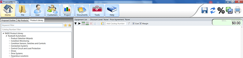
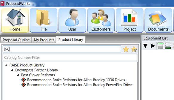
ProposalWorks has a keyword filter shown below. As you’ll see, there are two Encompass Partners for braking resistors, PowerOhm, and IPC Resistors. You can type in either company. For this example, we will use IPC Resistors as the vendor.
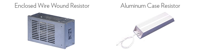
Post Glover owns IPC Resistors, as shown above. You will see two choices for brake resistors; the PowerFlex® has the chopper integral to the drive. The 1336 drives do not have a chopper, so the dynamic brake for a 1336 drive has the chopper and resistor both externally from the drive enclosed in a cage as a dynamic braking package.
The example below uses a PowerFlex drive. Variations of different PowerFlex drives have been around since 2000; these only require an external resistor.
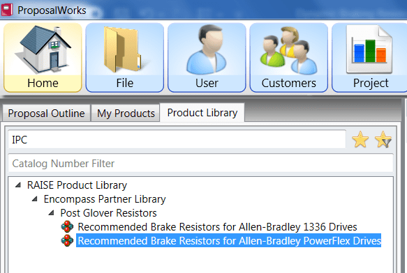
Click on the PowerFlex text, and the configuration screen appears to start your correct choice for the Rockwell Automation 10HP. Please notice the only math you have done is determined the amount of time the drive is braking (% Braking).
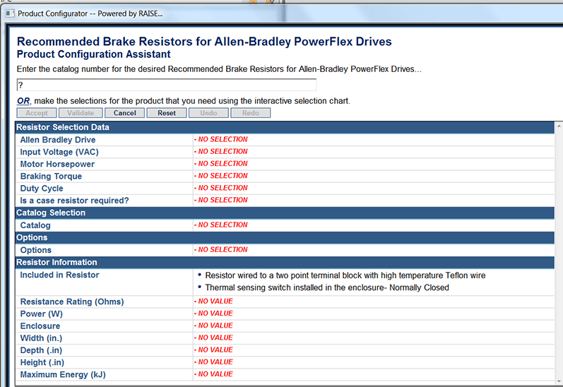
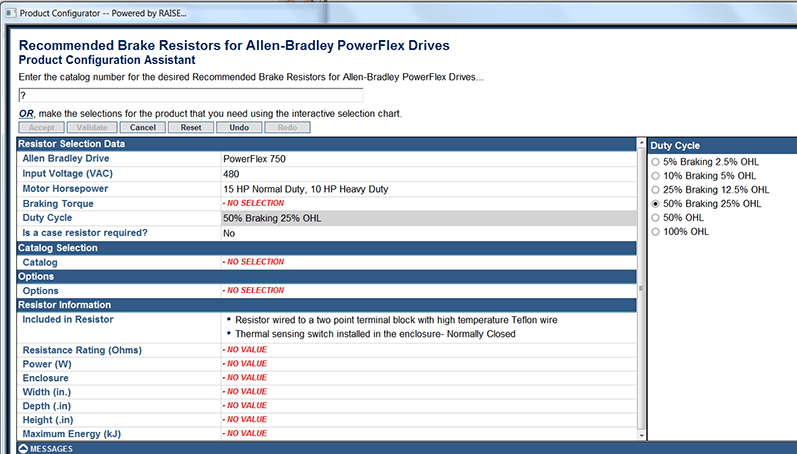
For this example, we have chosen a 10 HP heavy duty drive (not a pump or a fan, which is normal duty) at 480 VAC, and we must exceed 41.6% DC braking. So, we must choose the 50% DC braking. This choice comes with an overhauling load of 25% automatically. This is the rating for inertial loads that are influencing the motor and making it a generator back onto the DC bus (with no place to go yet) in the drive, preventing rapid deceleration.
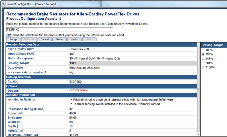
Now we will choose the % braking torque at the 50% braking level. This application requires the five stops at ten-second intervals over our two-minute window that we evaluated during our field study. We will choose 134% Braking Torque to the motor. This should stop the motor sufficiently and provide a similar amount of force than needed to accelerate the load.
The NEMA rating of all manufacturers with induction motors is 150% for a one-minute window. Out of the box from the factory, drives are programmed to 150% of their continuous amp rating (three contiguous numbers in the drive catalog number), not to the motor in the specific application. This can be adjusted if the drive horsepower is larger than the horsepower of the motor. Amps are congruent to torque, so this means we are stopping and starting the motor with approximately the same power at 134% deceleration and 150% acceleration.
In heavy-duty applications, please look at your motor nameplate information and set the current limit value in the drive to 1.5 x FLA of the motor. This will allow current flow during acceleration and deceleration to provide excellent motor torque. The design of the induction motor will allow for peak torque of motor for approximately 200% for a brief period of two to three seconds. The drive will integrate the current continuously at 150% under the curve for current (amps) going to and from the drive.
If the current exceeds the current limit value, the drive will clamp the amps going to the motor, reducing motor torque. Please keep in mind the current will flow to and from the DC bus of the drive output bidirectionally from the DC bus to the motor, and the current limit determines this amount.
Below are all the details ProposalWorks has provided after the duty cycle and braking torque are entered. Please check the ohms, voltage, and horsepower to make sure they are correct before ordering the part shown.
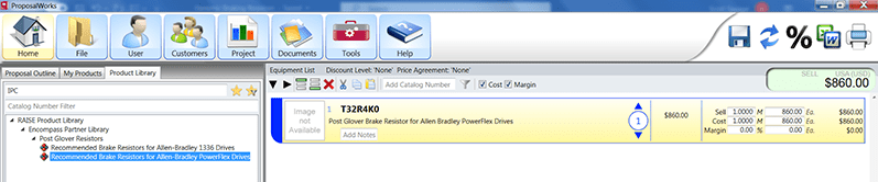
Accept the configuration, and the part will be added to the bill of materials in ProposalWorks.
Limitations Using Dynamic Braking Resistors
We all live under the laws of physics when it comes to motion, and how fast we can operate things like our machinery and automobiles, the energy and losses all must be accounted for when producing work. This holds true with large inertial loads, especially. If the duration of braking and the mass and diameters are excessive, it could lead to an engineered solution with banks of resistors in parallel.
This may be a situation where you may want to implement a software package called Engineering Assistant, which can be downloaded from the Rockwell Automation website. You will need to enter detailed information to get a viable solution (e.g., mass, radii, times, etc.) It is common to see the Engineering Assistant with the download of Drive and Motion Analyzer on the web page for Rockwell Automation, as well. A quick and easy way is just to Google search Rockwell Engineering Assistant.
The advent of the regenerative drive era has opened other solutions besides dynamic braking resistors. For example, the 755TR drive allows current flow bi-directionally to the power distribution, which the six pulse drive offering does not allow you to do. This may be a more efficient and more environmentally friendly way to handle the mechanics of a large centrifuge, dryer, or tumbler.
We Can Help
We are always here to assist with applications that may be extreme challenges for your facility. Please contact us if you are unsure, and don’t hesitate to add us to your team. Thank you so much for reading this blog, and good luck in your design utilizing braking applications!