
Blog > Automation > E300 Overload Relay Installation Concepts
E300 Overload Relay Installation Concepts
1/17/24 | Scott Savage, Senior Power Technical Consultant

Hi, everyone, and welcome to another post on the Automation Frontier Blog. The purpose of this post is to discuss the commissioning of an E300 Overload Relay using a ControlLogix or CompactLogix control.
The design of the product is different than the now-obsolete E1 overload because you can no longer “dial” in the motor overload value locally on the front of the unit.
Keep in mind this overload is more of a system approach, integrated in tightly with ethernet connectivity and the ability to transfer important data back to the enterprise.
There is a diagnostic station to enter programming features to the overload prior to connecting to the Logix processor. This may be an option to consider for the interim period. Keep in mind that you also have to start the motor via the keypad after entering the FLA of the motor until the Logix is connected.
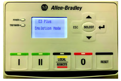
DIAGNOSTIC STATION
193-EOS-SDS
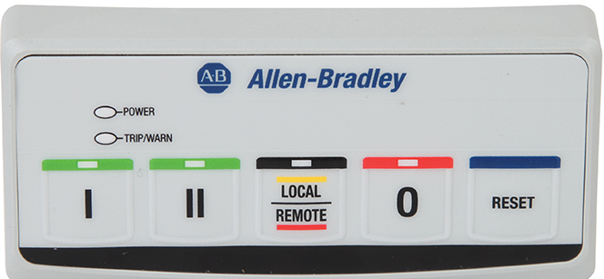
OPERATOR STATION ONLY
193-EOS-SCS
Please keep in mind that existing programs can be stored in either the operators station or the diagnostic station. To upload the parameter file, press the “off” button and “reset” button simultaneously for three seconds. To download the parameter file, press the “off” button and “local/remote” button simultaneously for three seconds. Once the lights on the station cycle back to a green status, the data transfer is complete. Make sure you frequently backup the program.
For more information, refer to document 193-061D.
Now, let’s look at the three modules that comprise the E300:
Sensing Module
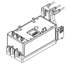
The sensing module electronically samples data about the current, voltage, power, and energy that are consumed by the electric motor internal to the module. You can choose from one of three varieties of the sensing modules depending on the motor diagnostic information that is needed for the motor protection application:
- Current Sensing
- Current and Ground Fault Current Sensing
- Current, Ground Fault Current, Voltage, and Power Sensing
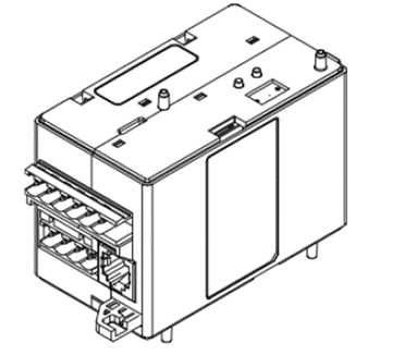
Control Module
The control module is the heart of the E300 relay and can attach to any sensing module. The control module performs all protection and motor control algorithms and contains the native I/O for the system. It has two varieties:
- I/O only
- I/O and protection (PTC and External Ground Fault Current Sensing)
The control module is offered in three control voltages:
- 110… 120V AC, 50/60Hz
- 220… 240V AC, 50/60Hz
- 24V DC
Communication Modules
The communication module allows the E300 relay to be integrated into an automation system, and it can attach to any control module. All communication modules allow you to set the node address with rotary turn dials, and it provides diagnostic status indicators to provide system status at the panel.
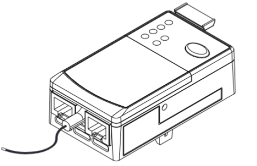
The E300 EtherNet/IP Communications Module has two RJ45 connectors that function as a switch. You can daisy chain multiple E300 relays with Ethernet cable, and the module supports a Device Level Ring (DLR).
Figure 3 – EtherNet/IP Communication Module
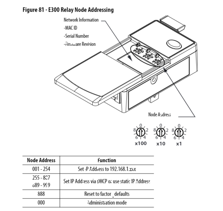
Setting IP Address with Rotary Switches
The default network using the switch approach is 192.168.1.x (unique IP node).
Step 1 – We will use our node address – in this example we’ll use 10 (192.168.1.10)
Step 2 – Rotate the middle rotary switch under cover to “1”
Step 3 – Cycle power to lock node address to communication module
Step 4 – Rotate the switch back to “0” to go to configuration mode to use web browser
Step 5 – Type the IP address 192.168.1.10 into the browser and your webpage will load
Using BootP Server and Configure any IP Address You Want
BootP Server is a utility that comes with your Studio 5000 software. You can use it to set any IP address with an ethernet connection and a laptop. Search for the BootP application on your laptop. Set the Local Area Adapter on the laptop to the subnet your E300 will be operating on. i.e. 192.10.10.10 (different than rotary switches).
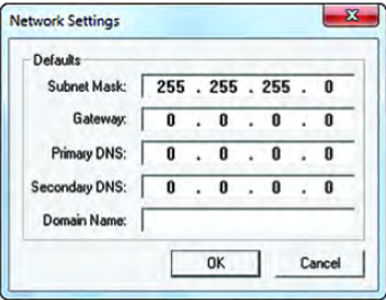
Open the BootP app and type in the minimum Subnet Mask – use 255.255.255.0 if you are doing a basic flat network.
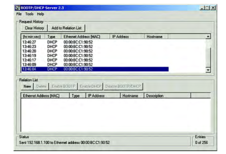
Click “OK.” The Request History Panel displays the hardware addresses of modules issuing BootP or DHCP requests.
Double-click the MAC address of the module to be configured
Note: The MAC address is printed underneath the sliding front cover of the E300 relay EtherNet/IP Communication Module. The format of the hardware address resembles 00-0b-db-14-55-35.
The New Entry window appears with the module’s Ethernet Address (MAC).

Type the IP address, host name, and a module description, then click “OK.” Cycle power to the E300 relay EtherNet/IP Communication Module.
To permanently assign this configuration to the module, select the module in the Relation List panel and click Disable BOOTP/DHCP.
Next, open RSLinx. Use ethernet/IP driver, and you should see after cycling power to E300.
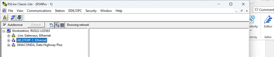
E300 should show up on the right in network (E300 not shown in the above example). Your network local adapter on the laptop needs to be on the same network.
If you see the specific E300 the IP is set.
Hint: if you have multiple E300s, unplug all other units and program one at a time.
Web Server Security and System Password
The E300 EtherNet/IP Communication Module’s web server allows you to view any diagnostic and parameter information. Security measures are built into the web server to deter a malicious user from making any unwanted EtherNet/IP system changes and E300 configuration parameter edits. When you attempt to make an EtherNet/IP system change or E300 configuration parameter edit, you are prompted to enter a username and password.
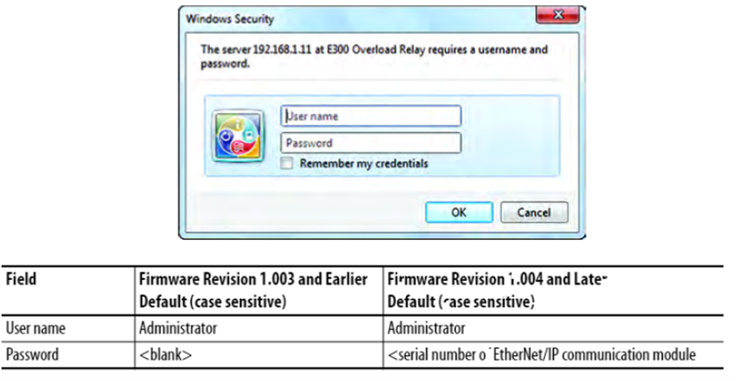
You can find the module serial number on the label of the EtherNet/IP communication module. We recommend that you change the password for the Administrator username, which can be done on the configuration web page.
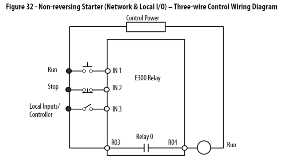
Determine Control Scheme for Starter (Non-Reversing)
Configure an E300 Relay in a Logix Project
Use the Studio 5000 Logix Designer application to configure an E300 relay in a Logix project. Download and install the Add-on Profile. Download firmware, associated files (such as AOP, DTM, and EDS), and access product release notes from only the Product Compatibility and Download Center.
Go online with the controller and right click on the Ethernet tree. Select either Discover Modules or New Module.
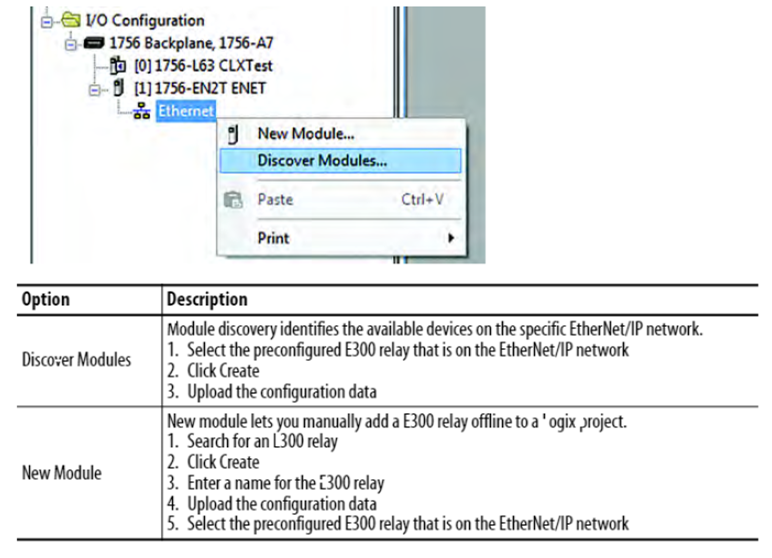
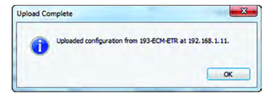
If the upload is successful, a display appears, indicating the success of this command. Press OK to continue.
If the upload is not successful due to communication errors, a display appears indicating that there was an upload error, and the device uses default settings. Click OK to continue. Identify and fix the reason for the communication error and press Upload aga, or press Cancel to remove any module definition changes.
If the upload is not successful due to an E300 configuration trip, a display appears indicating that the profile is using its existing settings. Click OK to continue. Read parameters 38 and 39 from the E300 relay to determine the reason for the configuration trip. Fix the issue and press Upload again, or press Cancel to remove any module definition changes.
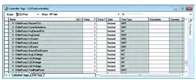
Access I/O Data
To access the data provided by the E300 relay EtherNet/IP Communication Module, navigate to the input tags.
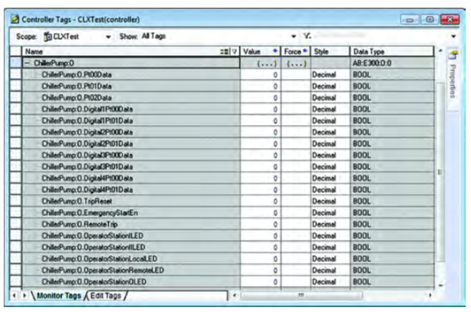
To control the output relays or issue a remote reset command to the E300 relay, navigate to the output tags.
This concludes the blog on the E300 Overload Relay Installation Concepts. We strongly encourage you to seek out your Industrial Control Technical Consultant in your area or contact us here, for a deeper dive into a data-intensive E300 journey. This blog post gives you the concepts to start on your journey. Please refer to the following publication for more information at the Literature Library on the Rockwell Automation website: