
Blog > Automation > Complications with Multiple Motors on One VFD
Complications with Multiple Motors on One VFD
5/4/22 | Scott Savage, Rexel Technical Consultant
Blog > Automation > Complications with Multiple Motors on One VFD
5/4/22 | Scott Savage, Rexel Technical Consultant
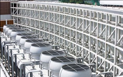
There are so many instances where original equipment manufacturers incorporate multiple motors on one AC drive as their design. Kilns are a typical example of many drives on one VFD. Another example is cooling towers that need to run at the same speed, leaving the design simple and the motors operating at the same hertz value from the drive (same speed).
The design is simple and cost-effective. However, as the system ages, it can be difficult to troubleshoot. There are things we will discuss in this blog that owners should be aware of during and after the installation.
This blog will review facts about multiple motors wired to one VFD (Variable Frequency Drives) and discuss solutions to these reoccurring problems.
The first topic of discussion is the lengths between each motor and the drive. Operations are dealing with most systems after the fact and have reoccurring issues with motor failure. It may take months or even longer periods of time for this to happen.
Many blogs discuss the simplicity and cost savings of one drive to multiple motors and do not discuss some of the other issues that may occur. Let’s take a deeper dive into some of the requirements involved with these systems.
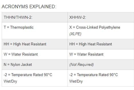
THHN/THWN-2 is a thermoplastic product, while XHHW-2 features thermoset insulation.
Thermoplastic:
Thermoset:
Now you have inspected the cable or hopefully followed the ground rules before installation. Let’s understand the concept of motor lead lengths and how they affect drive/motor challenges.
Now you know the total distance of all the motor leads here are basic rules you need to follow (ballpark figures) when it comes to multiple motors on one VFD drive:
Reflected wave is a phenomenon with long lead lengths to the motor. Voltage doubles and sometimes triples at the first turn of the motor. This will cause corona (bubbling of the dielectric in the windings) ground faults will occur and fault the drive. Non-shielded cable that is not twisted has great capacitance – then the waveform strikes the motor which is high in inductance and reflects back on the output wires. Even wires near the motor may exhibit heat issues and even corona as well as the motor windings.
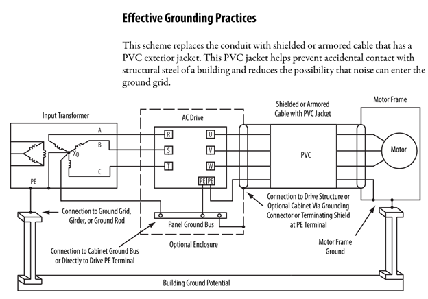
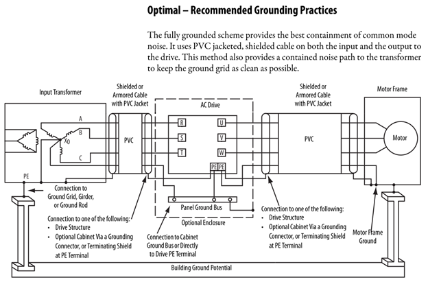
The second phenomenon that happens is common-mode noise, the longer the distance the greater the magnitude of noise. It is important to practice good grounding practice. Noise shortens the life of the drive and disrupts instrumentation and controllers (PLCs or BMS systems). Poor shielding and grounding allow high frequency circulating currents through surfaces of wires, frames of equipment, and yes - without shielding broadcast airborne noise. These currents need to go back to the point of origin (the drive) to make all currents cancel to a value of “0”. Good grounding directs the noise back to the drive and not throughout the system.
The system shows sign of degradation over time and burdens the maintenance staff. They are frustrated and repeatedly placing quick bandages on a hemorrhage.
Many articles promote this system design; there are consequences in taking this approach. The fact of the matter is with individual drives (which now costs the same or less) the one drive fits all approach may be something to consider on an upgrade. This is one solution versus adding dv/dt filters or sine wave filters.
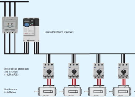
One drive and multiple motors must run in V/hz mode, Sensorless Vector and Flux Vector are one motor-only models. Shown below is the example normally seen. The motor overload relays must be added to each motor lead to protect the motor from excessive amps. This adds to the cost of the installation. A drive on each motor drive protects the motor and overload is not required. If the system is retrofitted with individual drives the branch protection (circuit breaker) does not change and the overload relays would be removed. Now you know which motor has the ground fault. Downtime is severely reduced, and the entire system does not go down and can be run at reduced capacity till problem is solved. (some have done exactly this with no problems afterward). Motors do not have to be the same HP.
Your facility decides not to go with individual drives. “We have never had problems in the past”. Motors fail and is routine maintenance they say. Please have the motor examined by an EASA motor repair shop and determine the cause – are the first turns in the motor burned up? If they are it is reflected wave. All the motors are decaying due to long lead lengths and rough waveforms.
A sinewave filter will reformulate the rough waveform back into a sinusoidal waveform. Companies like TCI (Transcoil) build a sine wave filter called MotorShield that can be wired close to the drive output and then go to the motors. Reflected wave does not exist after the retrofit. Horizon Solutions has helped customers install these units and they have run for many years without a problem.
There is just not one proven solution if you have an existing system. Please consider all the topics discussed in this blog and decide what works best for you. If you are designing a new system, or upgrading an existing system, these ground rules (excuse the pun) could save hours of aggravation and downtime. Horizon Solutions encourages you to practice good grounding not just for electrical code but both code and noise mitigation (the hidden problem). Reflective wave is destructive and not so hidden. If motors are failing dig deeper and hopefully you find this article on the web.
Enjoy this discovered article and contact us for more information.
Special thanks to Rockwell Automation®, automation.com, Istock, and OmniCable for images.