
Blog > Automation > PID Pump Control Using Exclusive Pump Control
PID Pump Control Using Exclusive Pump Control
11/16/23 | Scott Savage, Senior Power Technical Consultant
E = SP-V
E = Error between Setpoint and Process Variable (transducer)
SP = Setpoint programmed in Parameter 1070
PV = Feedback device embedded in the system
What is a PID Controller?
A PID controller, short for proportional–integral–derivative controller, is a feedback-based control loop extensively employed in industrial systems and various applications demanding continuous modulation. The controller calculates the error value, the difference between the desired setpoint and the measured process variable, and applies corrections based on proportional (P), integral (I), and derivative (D) terms. This ensures accurate and responsive adjustments to control functions. For instance, in a car's cruise control system, the PID algorithm maintains the desired speed by regulating the engine power output, minimizing delays and overshoots during speed changes.
The PID concept, initially developed for automatic ship steering in the 1920s, found widespread use in manufacturing for pneumatic and electronic controllers. Today, it is a universal solution for applications requiring precise and optimized automatic control. The controller's three terms (P, I, and D) each play a unique role: P responds to the current error, I integrates past errors over time, and D estimates the future error trend. Loop tuning is crucial to balance these effects, with constants (Kp, Ki, Kd) derived for each application based on external loop characteristics. The control action is typically direct, meaning a positive error leads to a positive control output correction, unless the system requires reverse action for specific control schemes or final control elements.
Understanding PID Output
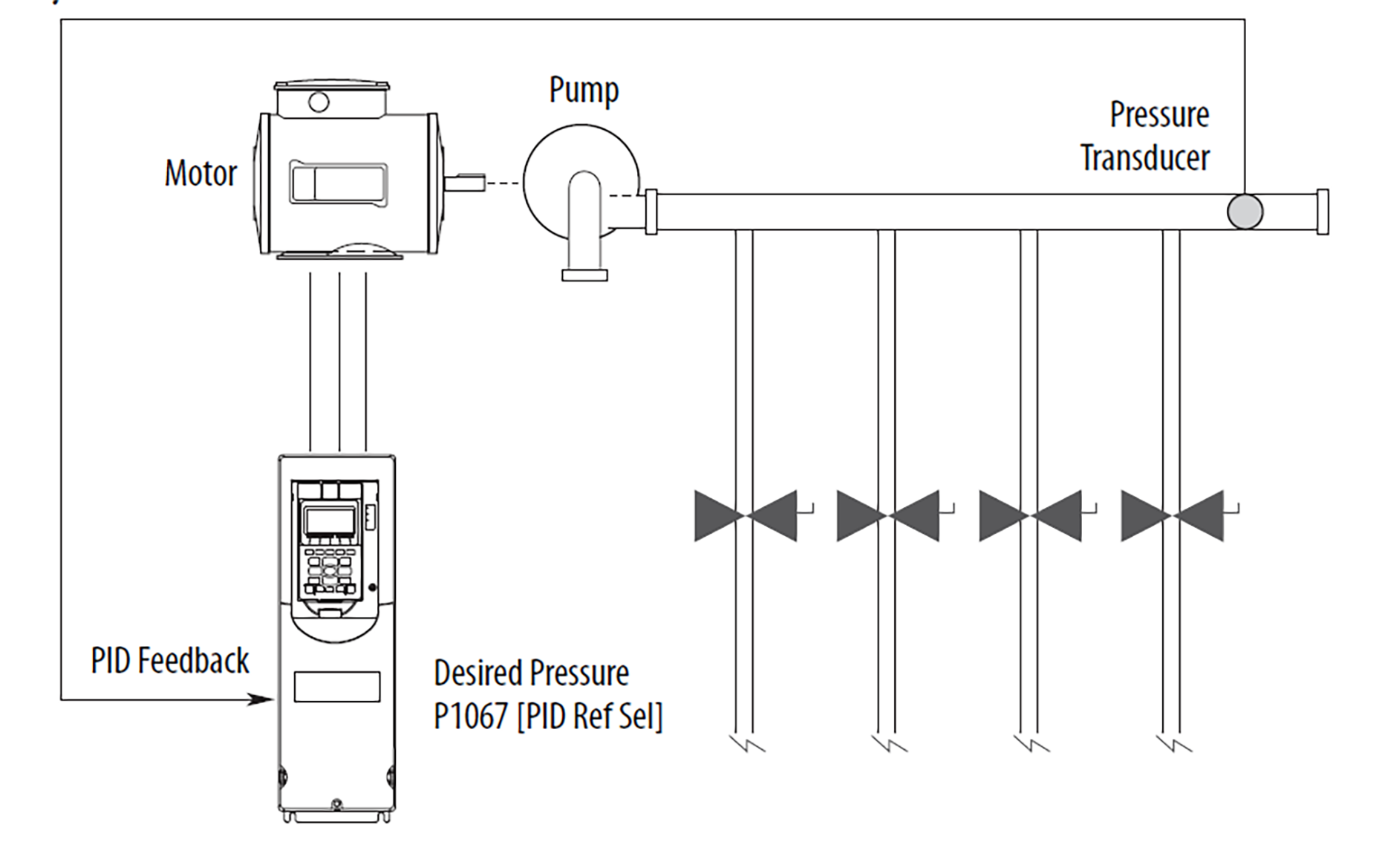
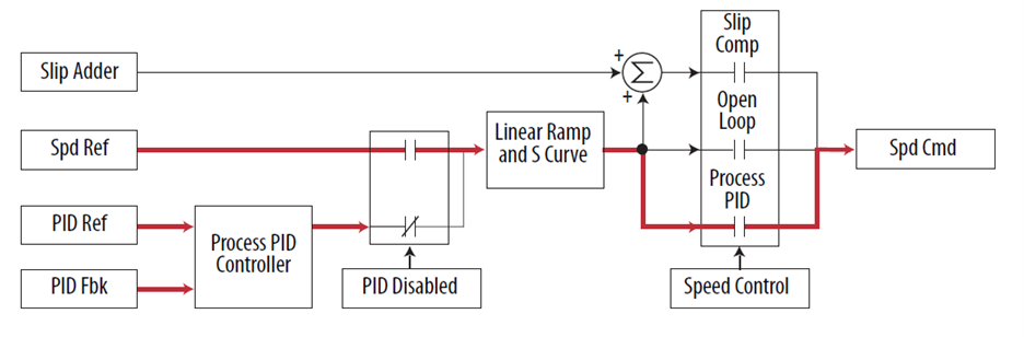
When additional valves in the system are opened and the pressure in the system drops, the PID error alters its output frequency to bring the process back into control. When the PID is disabled, the commanded speed is the ramped speed preference.
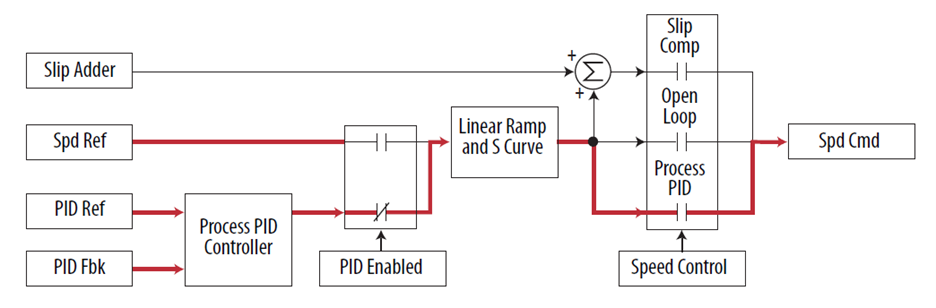
When the PID is enabled, the speed reference is disconnected and PID Output has exclusive control of the commanded speed, passing through the linear ramp and S curve.
PID Output Select
Parmenter 1079 [PID Output Sel]
- “Not used” (0) – PID output is not applied to any speed reference.
- “Speed Excel” (1) – PID output is the only reference applied to the speed reference.
- “Speed Trim” (2) – PID output is applied to the speed reference as a trim value. (Default)
- “Torque Excl” (3) – PID output is only reference applied to torque reference.
- “Torque Trim” (4) – PID output is applied to torque reference as a trim value.
- “Volt Excl” (5) – PID output is only reference applied to voltage reference.
- “Volt Trim” (6) – PID output is applied to voltage reference as a trim value.
Speed Exclusive Control is the Preferred Mode in Parameter 1079
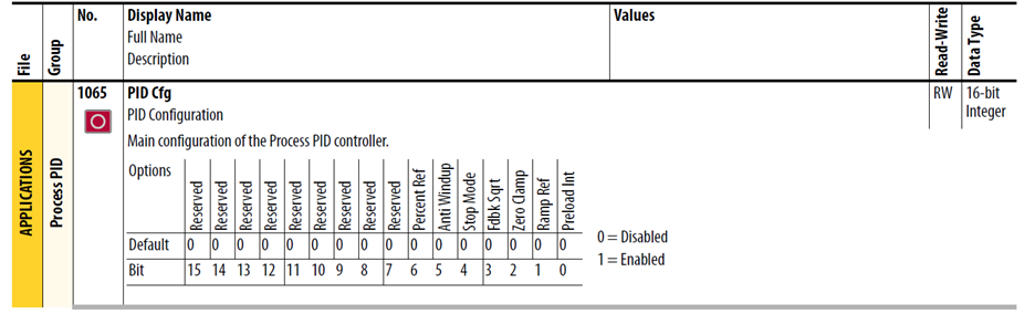
PID Configuration – Parameter 1065 [PI Cfg] is a set of bits that select various models of operation. The value of this parameter can only be changed while the drive is stopped.
PID Preload
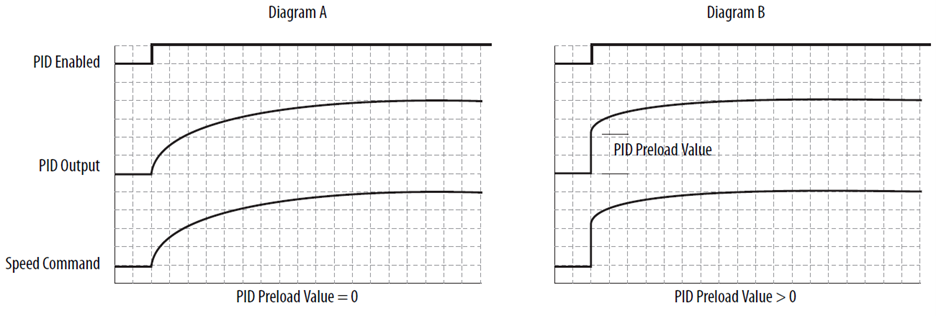
This feature steps the PID Output to a preload value for better dynamic response when the PID Output is enabled. Refer to the diagram below. If PID is not enabled, the PID integrator can be initialized to the PID Preload Value or the current value of the commanded speed. The operation of Preload is selected in the PID configuration parameter. By default, Preload Command is off and the PID Load Value is zero, causing a zero to be loaded into the integrator when the PID is disabled. As shown in Diagram A below, when the PID is enabled the PID output starts from zero and regulates to the required level. When PID is enabled with PID Load Value is set to a non-zero value the output begins with a step as shown in Diagram B below. This can result in the PID reaching steady state sooner, however if the step is too large the drive can go into current limit and extend the acceleration.
Preload command can be used when the PID has exclusive control of the commanded speed. With the integrator preset to the commanded speed there is no disturbance in commanded speed when PID is enabled. After PID is enabled the PID output is regulated to the required level.
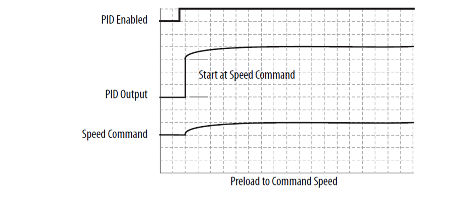
When the PID is configured to have exclusive control of the commanded speed and the drive is in current limit or voltage limit the integrator is preset to the commanded speed to that it knows where to resume when no longer in limited.
Ramp Ref
The PID Ramp Reference feature is used to provide a smooth transition when the PID is enabled and the PID output is used as a speed trim (not exclusive control). When PID Ramp Reference is selected in the PID configuration parameter, PID is disabled, the value used for the PID reference is the PID feedback. This causes the PID error to be zero. Then when the PID is enabled, the value used for the PID reference ramps to the selected value for PID reference at the selected acceleration or deceleration rate. After the PID reference reaches the selected value, the ramp is bypassed until the PID is disabled and enabled again. S-curve is not available as part of the PID linear ramp.
Zero Clamp
This feature limits the possible drive action to one direction only. Output from the drive is from zero to maximum frequency forward or zero to maximum frequency reverse. This removes the chance of doing a “plugging” type of operation as an attempt to bring the error to zero. This bit is active only in trim mode.
The PID has the option to limit operation so that the output frequency always has the same sign as the master speed reference. The zero clamp option is selected in the PID Configuration parameter. Zero clamp is disabled when PID has exclusive control of speed command.
For examples, if master speed reference is +10 Hz and the output of PID results in a speed adder of -15 Hz, zero clamp limits the output frequency to not become less than zero. Likewise, if master speed reference is =10 Hz and the output of the PID results in a speed adder of +15 Hz, zero clamp limits the output frequency to not become greater than zero.
Feedback Square Root
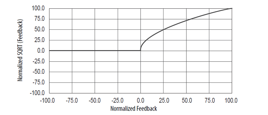
This feature uses the square root of the feedback signal as the PID feedback. This is useful in the processes that control pressure because centrifugal fans and pumps vary pressure with the square of speed.
The PID has the option to take the square root of the selected feedback signal. This is used to linearize the feedback when the transducer produces the process variable squared. The result of the square root is normalized back to full scale to provide a consistent range of operation. The option to take the square root is selected in the PID configuration parameter.
Stop Mode
When P370/371 [Stop Mode A/B] is set to 1 “Ramp” and a Stop command is issued to the drive, the PID loop continues to operate during the decel ramp until the PID output becomes more than the master reference. When set to 0 “Coast,” the drive disables PID and performs a normal stop. This bit is active in Trim mode only.
Anti-Wind Up
When P1065 [PID Cfg] Bit 5 “Anti Windup” is set to 1 “Enabled” the PID loop automatically prevents the integrator from creating an excessive error that could cause loop instability. The integrator is automatically controlled without the need for PID Reset or PID Hold inputs.
Percent Ref
When using Process PID control the output can be selected as percent of the Speed Reference. This works in Speed trim mode only, not in Torque Trim or Exclusive mode.
Example
Percent Ref selected, Speed Reference = 43 Hz, PID Output = 10% Maximum Frequency = 130 Hz. 4.3 Hz is added to the final speed reference.
Percent Ref not selected, Speed Reference= 43 Hz, PID Output= 10%, Maximum Frequency= 130 Hz. 13.0 Hz is added to the final speed reference.
PID Control
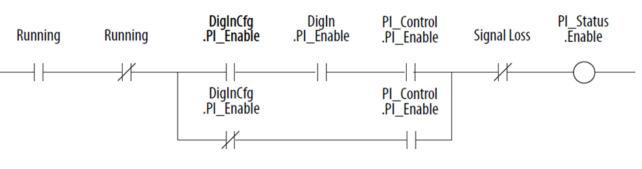
The PID loop can be enabled/disabled. The Enabled status of the PID loop determines when the PID regulator output is part or all the commanded speed. The logic evaluated for the PID Enabled status is shown in the following ladder diagram.
The drive must be in Run before the PID Enabled status can turn on. The PID remains disabled when the drive is jogged. The PID is disabled when the drive begins a ramp to stop, except when it is in Trim mode and the Stop mode bit in P1065 [PID Cfg] is enabled
When a digital input is configured as “PI Enable,” the PID bit of P1066 [PID Control] must be turned On for the PID loop to become enabled. If a digital input is not configured as “PI Enable” and the PIT Enable bit in [PID Control] is turned On, then the PID loop can become enabled. If the PID Enable bit of [PID Control} is left continuously, then the PID can become enabled as soon as the drive goes into Run. If analog input signal loss is detected, the PID loop is disabled.
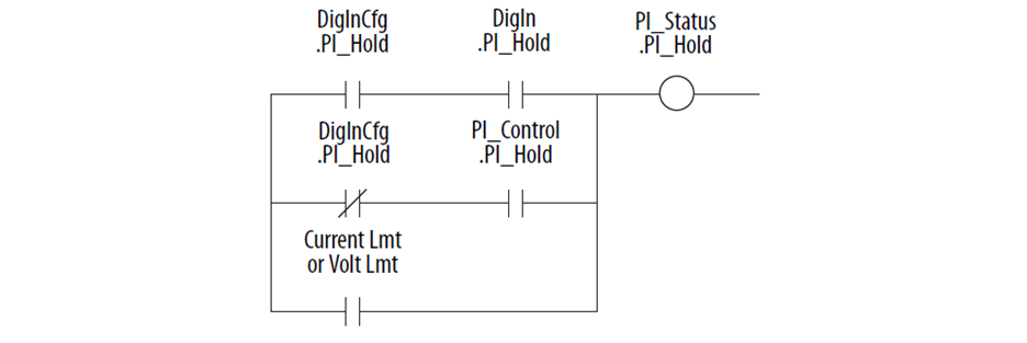
PID Hold
The Process PID Controller has the option to hold the integrator at the current value so if some part of the process is in limit the integrator maintains the present value to avoid windup of the integrator. The logic to hold the integrator at the current value is shown in the following ladder diagram. There are three conditions under which Hold turns on.
- If a digital input is configured to provide PID Hold and that digital input is turned on then the PID integrator stops changing. Note that when a digital input is configured to provide PID Hold that takes precedence over the PID control parameter.
- If a digital input is not configured to provide PID Hold and the PID Hold bit in the PID Control parameter is turned on the PID integrator stops changing.
- If the current limit or voltage limit is active, then the PID is put into Hold.
PI Reset
This feature holds the output of the integral function at zero. The term “anti windup” is often applied to similar features. It can be used for integrator preloading during transfer and can be used to hold the integrator at zero during “manual mode.”
For example, a process whose feedback signal is below the reference point, creating error. The drive increases its output frequency in an attempt to bring the process into control. If, however, the increase in drive output does not zero the error, additional increases in output are commanded. When the drive reaches programmed Maximum Frequency, it is possible that a significant amount of integral value has been “built up.” (windup). This can cause undesirable and sudden operation if the system were switched to manual operation and back. Resetting the integrator eliminates this windup.
Invert Error
This feature changes the “sign” of the error, creating a decrease in output for increasing error and an increase in output for decreasing error. An example of this is an HVAC system with thermostat control. In summer, a rising thermostat reading commands an increase in drive output because the cold air is being blown. In winter, a falling thermostat commands an increase in drive output because warm air is being blown. The PID has the option to change the sign of the PID Error. This is used when an increase in feedback needs to cause an increase in output. The option to invert the sign of PID Error is selected in the PID Configuration parameter.
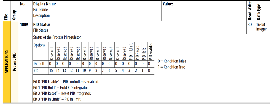
PID Status – P1089 [PID Status] parameter is a set of bits that indicate the status of the process PID controller.
PID Reference and Feedback
The selection of the source for the reference signal is entered in P1067 [PID Ref Sel]. The selection of the source for the feedback signal is selected in P1072 [PID Fdbk Sel]. The reference and feedback have the same limit of possible options.
Options include DPI adapter ports. MOP, preset speeds, analog inputs, pulse input, encoder input, and PID setpoint parameter.
The value used for reference is displayed in P1090 [PID Ref Meter} as a read only parameter. The value used for feedback is displayed in P1091 [PID Fdbk Meter] as a read only parameter. These displays are active independent of PID Enabled. Full Salve is displayed as +100.00%
PID Reference and Feedback Scaling
The analog PID reference can be limited by using P1068 [PID Ref AnlgHi] and P1069 [PID Ref AnlgLo]. [PID Ref AnlgHi] determines the high value, in percent, for the analog PID reference. [PID Ref AnlgLo] determines the low value, in percent, for the PID reference.
The analog PID feedback can be limited by using P1068 [PID Ref AnlgHi] and P1069 [PID Ref AnlgLo]. [PID Ref AnlgHi] determines the high value, in percent. For the PID feedback. [PID Ref AnlgLo] determines the low value, in percent, for the PID feedback.
PID Setpoint
This parameter can be used as an internal value for the setpoint or reference for the process. If P1067 [PID Ref Sel] points to this parameter, the value entered here becomes the equilibrium point for the process.
PID Error
The PID Error is then sent to the Proportional and Integral Functions, which are summed together.
PID Error Filter P1084 [PID LP Filter BW] sets up a filter for the PID Error. This is useful in filtering out unwanted signal response, such as noise in the PID loop feedback signal. The filter is a Radians/Second low pass filter.
PID Gains
Parameters P1086 [PID Prop Gain]. P1087 [PID Int Time]. And P1088 [PID Deriv Time] determine the response of the PID.
Proportional control (P) adjusts output based on the size of the error (larger error = proportionally larger correction). If the error is doubled, then the output of the proportional control is doubled. Conversely, if the error is cut in half then the output of the proportional output cut in half. With only proportional control there is always an error, so the feedback and the reference are never equal. [PID Prop Gain] is a unit less and defaults to 1.00 for unit gain. With [PID Prop Gain] set to 1.00 and PID Error at 1.00% the PID output is 1.00% of maximum frequency.
Integral control (I) adjusts the output based on the duration of the error. (The longer the error is present, the harder it tries to correct). The integral control by itself is a ramp output correction. This type of control gives a smoothing effect to the output and continues to integrate until zero error is achieved. By itself, integral control is slower than any applications require and therefore is combined with proportional control (PI). [PID Int Time] is entered in seconds. If [PID Int Time] is set to 2.0 seconds and PI Error is 100.00% the PI output integrates from 0 to 100.00% in 2.0 seconds.
Derivative Control (D) adjusts the output based on the rate of change of the error and, by itself, tends to be unstable. The faster that the error is changing, the larger the change to the output. Derivative control is usually used in torque trim mode and is usually not needed in speed mode.
For example, winders using torque control rely on PD control not PI control. Also, P1084 [PID LP Filter BW] is useful in filtering out unwanted signal response in the PID loop. The filter is a Radians/Second low pass filter.
PID Lower and Upper Limits/Output Scaling
The output value provided by the PID is displayed as +100% in P1093 [PID Output Meter].
P1083 [PID Lower Limit] and P1081 [PID Upper Limit] are set as a percentage. In exclusive or speed trim mode, they scale the PID Output to a percentage of P37 [Maximum Freq]. In torque trim mode, they scale the PID Output as a percentage of rated motor torque.
Example
Set the PID lower and Upper limits to +10% with the Maximum Frequency set to 100 Hz. This lets the PID loop adjust the output of the drive +10 Hz.
P1081 [PID Upper Limit] must always be greater than the P1082 [PID Lower Limit].
Once the drive has reached the programmed Lower and Upper PID limits, the integrator stops integrating and no further “windup” is possible.
PID Output Mult
P1080 [PID Output Mult] enables additional scaling of PID loop output.
Example
The application is a velocity-controlled winder. As the roll builds up, the output gain can be reduced to allow the dancer signal to be properly reacted to by the PID loop without changing the tuning of the PID loop.
PID Deadband
P1083 [PID Deadband] conditions the PID reference. If the PID reference has undesired rapid changes, the deadband can help smooth out these transitions.
Parameters of Interest in Review
Preparation Before the Loop is Activated
Be sure to test drive in hand prior to operation PID loop.
One way to see what the pressure is at a certain speed is to use the control screen shown below.
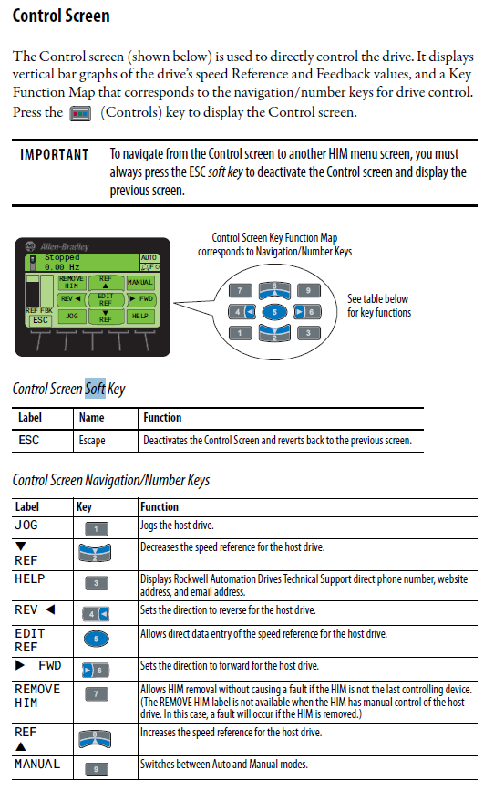
1) Toggle the drive manual mode (9 on keypad) on control screen
2) Edit the reference (5 on the keypad) to a Hz value
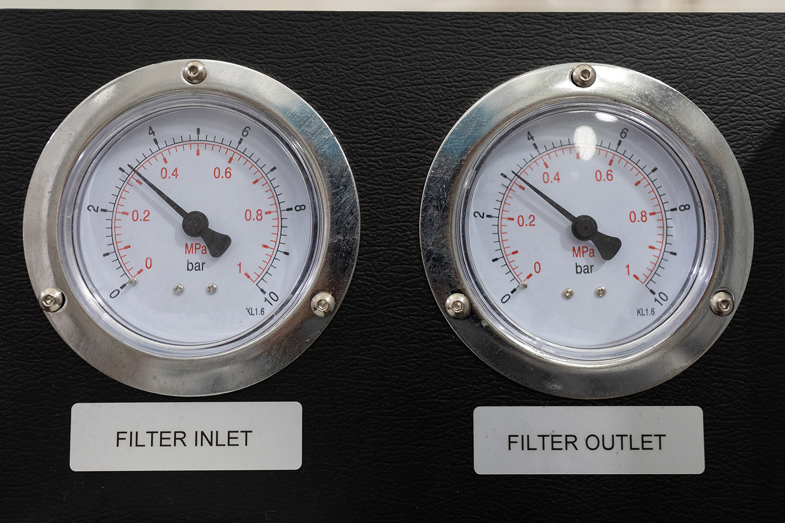
3) Start the drive, observe the speed check, and then check the gauge pressure status
4) Adjust speed with the reference button from keypad 5 until correct pressure
5) Document the correct speed on the control screen that you will match by adjusting the PID output select (1079) to achieve the speed for the correct pressure
6) Toggle the drive in auto mode (9 on keypad) on the control screen.
7) NOTE: Please keep in mind the square root of pressure should be the approximate speed of the drive (PID cfg 1065 Bit 3 value = 1)
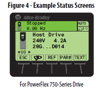
8) Use the status screen on drive to observe the drive speed as you adjust the PID setpoint (% of range) 1070
9) Match a speed in Hz to the speed of correct pressure when you were in the control screen in manual mode
10) Please keep in mind you can do this in cold turkey mode loop if you like and not use the control screen. Remember, though, if the loop starts in an unstable state, it is one extra thing to deal with all at once to find the correct pressure
11) Determine 0 – 10VDC or 4-20Ma type on channel, set jumper to 4-20mA if necessary
12) Identify the port the analog channel is assigned to and check the analog value on that channel in the port
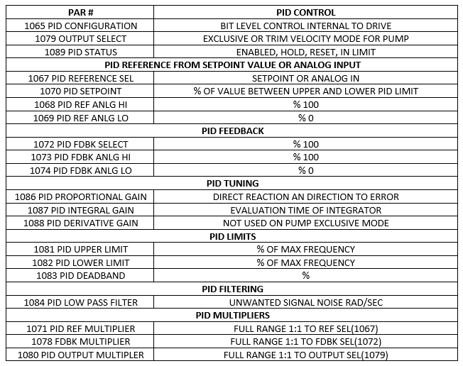
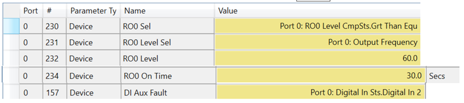
The suggested settings to start are shown in the graphic below. Non-defaults are highlighted in yellow.
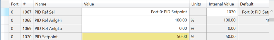
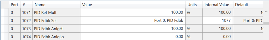
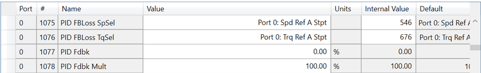
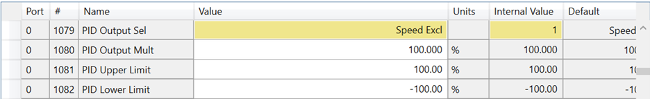
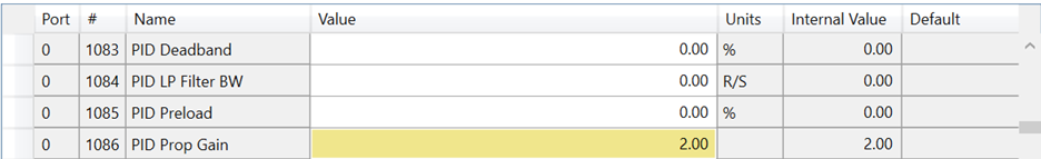
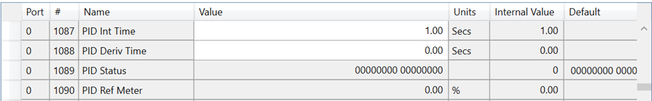

View Seen in Connected Components Workbench Software (FREE)
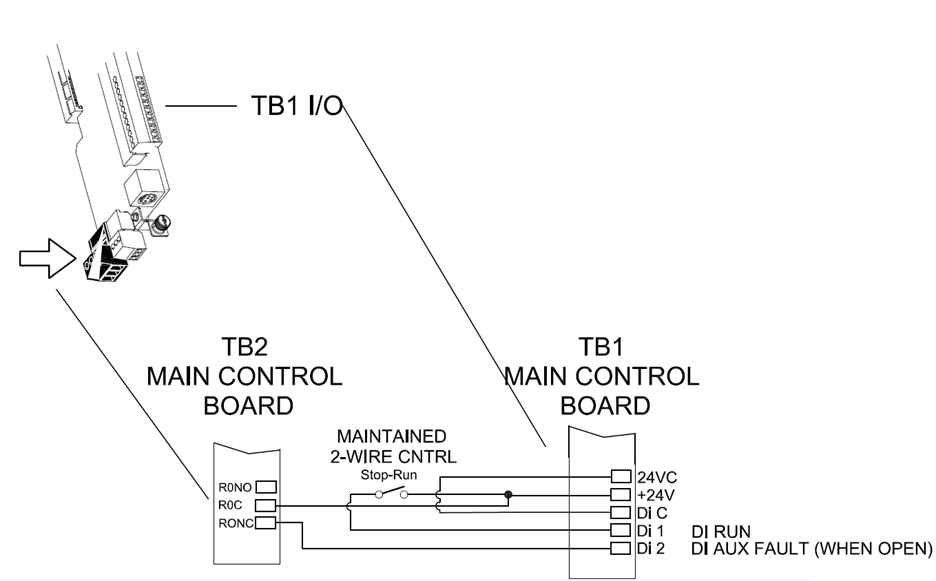
If you need to set a fault for wind up because of a broken pipe or the pump dead head condition, please consider assigning a relay with an assignment for output frequency. Use a comparison for greater than a certain value over a certain amount of time.
Thank you for viewing this blog from Rexel USA. For additional information please view and download the reference manual for the PowerFlex 750 series drive.
Search for (begins with): 750-RM
Open:

This document is an application guide in addition to the programming and installation manual for the PowerFlex F750. If you have questions or run into any challenges, please contact us today for support.