
Blog > Automation > Going from a Starter to a PowerFlex 4M Drive
Going from a Starter to a PowerFlex 4M Drive
12/7/21 | Scott Savage, Rexel Technical Consultant
Blog > Automation > Going from a Starter to a PowerFlex 4M Drive
12/7/21 | Scott Savage, Rexel Technical Consultant
This is the eighth part of my drive modernization series that has developed over the last few months. We are dedicated to reaching out to all our customers to possibly hit on a subject that meets your needs. So, we thought, what if some of you might want to replace across the line starters and move away from the “clickety-clack” devices to a solid-state, non-wearing drive that can do so much more than a starter.
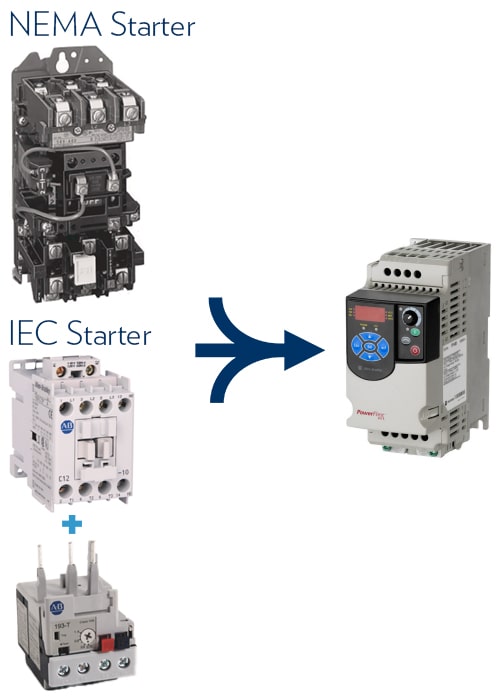
The other modernization series blogs talk about moving a mature drive in its life cycle to a newer style of drive. This blog is more of a conversion, going from a mechanical starter, which just mechanically closes and monitors amps for overload to a digital AC drive. The advent of small, cost-effective drives has made this possible even for small motor applications.
Size: Drive sizes in smaller frames have come down to some convenient sizes to replace contactors and overload components for DOL (Direct on Line) starters.
Wiring: Wiring of sealing contacts (which latch the starting circuit) and overload circuit to the starter (normally closed circuit) terminals are eliminated, making the replacement a simpler wiring scheme for troubleshooting later.
Wear: No moving mechanical parts and less maintenance.
Versatility: Full voltage starting does not give you the ability to adjust acceleration and deceleration times. FVNR (full voltage non-reversing) do not have the ability to change speeds or skip frequency bands to avoid harmonic resonance.
Energy Savings: Every little bit counts toward an inflated energy bill, even with small motors, it all adds up at your location. A centrifugal fan will save approximately 50% of the energy if the speed is reduced by 80%.
Modulation: The ability to change speeds for demanding applications is a major step forward to meeting the demands of dynamic systems.
Protection: A drive is not just a device that protects the motor from overload situations, it protects and helps troubleshoot motor circuit problems:
- Overload
- Overvoltage
- Overcurrent
- Imbalance
- Ground Fault Protection
Metering: The PowerFlex® 4M AC drive displays amps, volts, etc. without having to check with a multimeter.
Safety: Mounting the keypad on the door of the enclosure provides more freedom to troubleshoot without having to suit up and exposure to high-voltage electrical components.
Troubleshooting: Reduce troubleshooting time by allowing the drive to evaluate the motor conditions and present a “fault” with information that leads to a solution quickly.
- Fans & Pumps
- Conveyors
- Mixers
- Augers
- Packaging
- Stackers
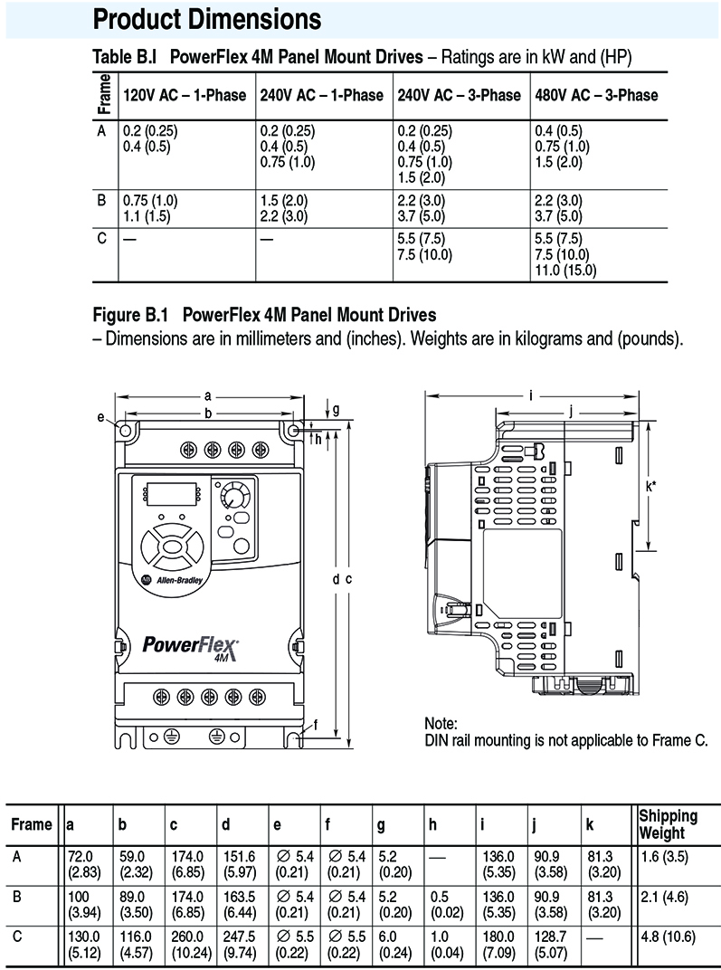
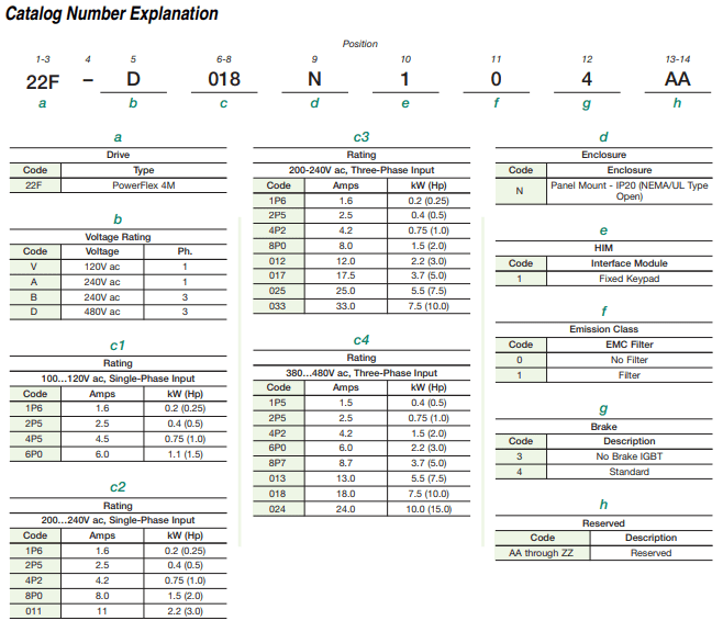
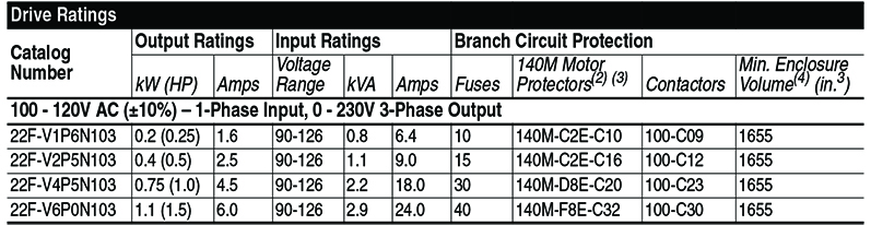
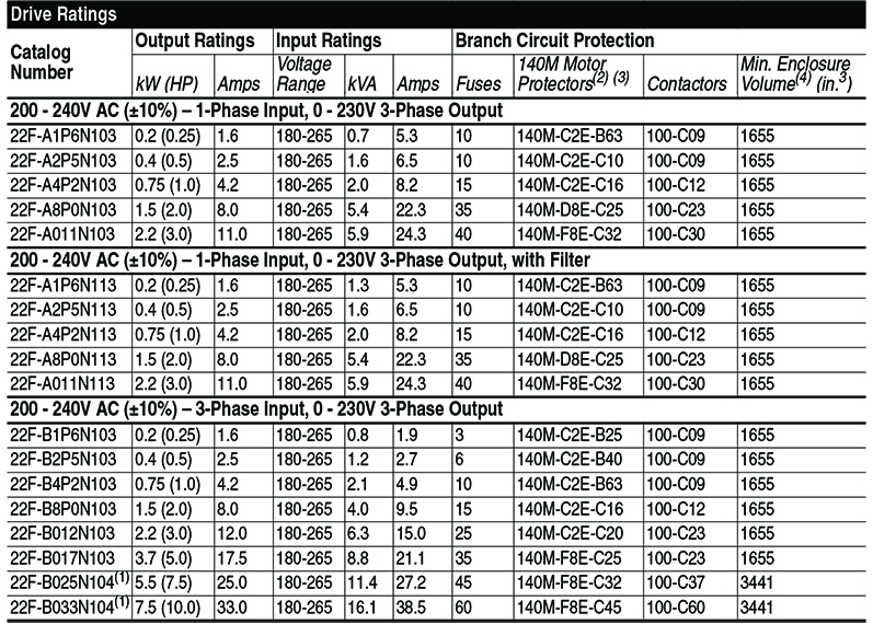
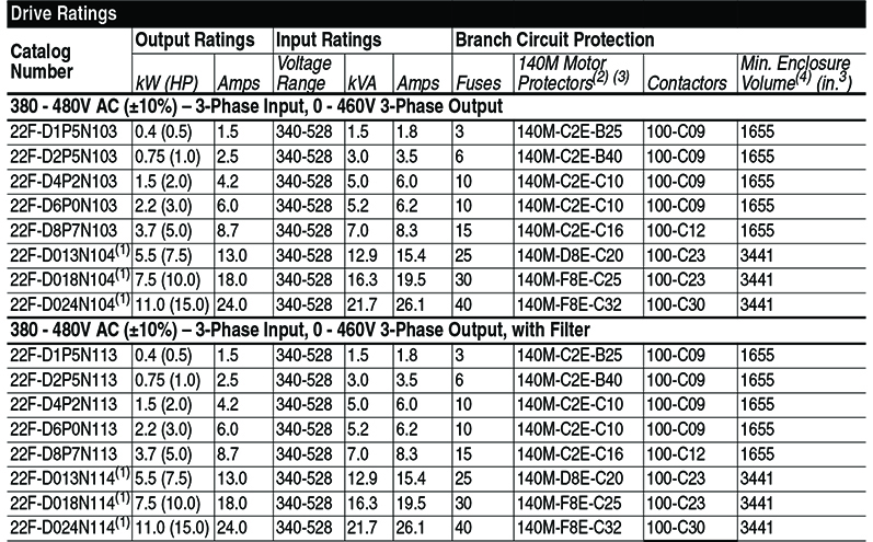
There are a variety DOL starters on the market, please take the time to check the dimensions of the existing starter and make sure the PowerFlex 4M drive will fit.
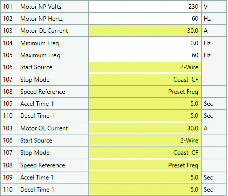
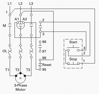
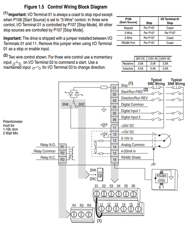
Start Source P106 (shown above) in most conversions to a two-wire or three-wire wiring scheme. An illustration of a three-wire standard wiring scheme is shown below. This shows a momentary start and momentary stop pushbutton. Three-wire control drops out the starter circuit upon power failure and must be started manually after power is restored. Two-wire control resumes starter after power failure used commonly on unattended pump stations.
Speed Reference P108 can be set to a preset speed if the drive runs at a constant speed. Here are the terminal inputs involved shown in the PowerFlex 4M drive user manual 22F-UM001-EN-P found on the Rockwell Automation® Literature Library.
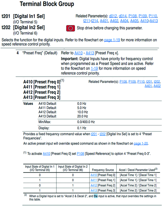
So, that is with no wires on any inputs Preset “0” P410 can be programmed with a value of “30,” which commands the drive to run at 30Hz speed (half of the base speed).
If the drive needs to modulate (change speeds to a process), the Preset Speed philosophy probably will not work. The Speed Reference P108 should be set to “0-10V” or for long distance (over 30 ft) use “4-20mA.”
Since the overload relay on your starter is now replaced by a parameter internal to drive, all you need to do is program P103 Motor OL Current to the proper motor amps. How do you get that data? It is the amps displayed on the motor nameplate. Type the amps into the parameter and your motor is protected.
The PowerFlex 4M drive has top entry wiring just like the starter terminal locations prior to the installation. The output on the bottom of the starter is identical to the drive bottom terminals and go to the motor. The contactor section and the overload relay either NEMA or IEC starter style are now eliminated and replaced with the drive. Wires do not need to be replaced to reach to new drive terminals.
A1 is the positive side of the coil, A2 is the common side of the coil. When the coil is energized, A1 has control power provided to the terminal and A2 has a connection to the common. If the overload relay opens due to too much current to the motor, the coil will de-energize. If the stop button is depressed while running the coil will de-energize.
If the overload (95 and 96) is reset (N.C.) and the start button is momentarily depressed. Terminals two and three on the starter will “seal” (latch) and remain closed until the coil circuit is interrupted by the stop button or the overload.
So, what happens if you do not have a momentary start/stop pushbutton setup for your starter control wiring? What if you have a maintained ON/OFF selector switch?
Always remember, drives are the most precise way to control drives. This is a very simple, basic drive. For those of you who have never programmed a drive, this is a great drive to start on.
Some other literature you may be interested in from Rockwell Automation’s Literature Library:
- 22F-UM001-EN-P PowerFlex User Manual
- 22F-TD001-EN-P PowerFlex Technical Document
Thank you for your interest in drive blogs. We hope these are of benefit to you now and in the future! If you have any questions or requests, contact us today!