
Blog > Automation > 5 Safety Control System FAQs Answered
5 Safety Control System FAQs Answered
2/22/17 | Tom Hopkins, Rexel Technical Consultant
Blog > Automation > 5 Safety Control System FAQs Answered
2/22/17 | Tom Hopkins, Rexel Technical Consultant
This is part two of a two-part series. Don’t miss part one: 5 Machine Safety FAQs Answered.
Let’s quickly review some of the points from part one:
In this article, you’ll focus on how to set up a safety control system with regard to machine safety. Before we get into the next four FAQs, let’s quickly delve into risk reduction measures, safety-related parts of the control system, and ISO 13849 and performance levels. Below is a table from the ISO standard showing the process of risk identification and reduction.
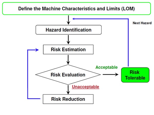
Once you have identified risks and quantified them, the next step is actionable changes towards risk reduction. Risk Reduction can be accomplished in different ways: (1) eliminate the hazard from your system (2) safeguarding, add physical guards to or around the hazard and (3) use PPE and train employees on best practices.
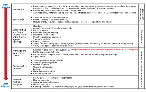
Some methods are preferred to others. This chart, from ANSI RIA TR15.06.306, does a good job of highlighting some methods of risk reduction measures and correlating them to a scale of effectiveness. Obviously, it’s best to eliminate the hazard, but if not possible, the next best option is working within your Machine Controls. This is called the “Safety-Related Parts of the Control System”, referred to within the standards as the SRP/CS.
Before we go any further, some quick background and terminology may be helpful. If you have a high level of familiarity with controls, you may already know some or all of this – but it can be a helpful refresher. We certainly encourage most users to let the standards guide you.
Many people have heard the terms Category 3 (Cat 3) or Category 4 (Cat 4) when talking about machine safety. The standard EN954-1 introduced category levels in 1997. This standard covered the fact that you could have a fault in your controls that might jeopardize safety. If there is a fault somewhere in the controls, how does one assure the system will perform as designed? Fundamentally a higher Category level added two things to create fault tolerance to the circuit:
In 2006, ISO 13849-1 superseded EN954 by adding to it. What was added and why? This addressed the scenario that a user could have a great circuit design but be utilizing low quality or unreliable components. That system would not be reliable. ISO 13849 also covers how to assure that the safety circuit is actually ready for a demand, through monitoring.
Three things were added in ISO 13849:
The ISO 13849 standard uses the term “Performance Levels” to rate the safety circuit. Occasional, Performance Levels is referred to as “PL”. Performance levels are rated ‘a’ thru ‘e’, where ‘e’ is the highest level. If you already understand Category ratings, the following table might be helpful in relating to Performance Levels:
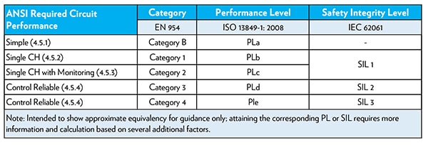
You can see in the table there is an approximate equivalency between Categories and Performance Levels. Also shown in the table are the ANSI term of “Control Reliable”, or the EN62061 standard term of “SIL”. But to avoid confusion, we will not introduce other standards. We will stay focused on our subject of setting up your controls.
OK, we covered a lot of technical details above. Take a breath, it’s not as complicated as it sounds. What it boils down to is this:
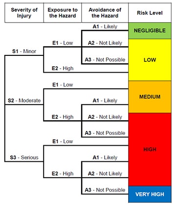
The higher the calculated risk, the higher the performance level is required of the controls. So, how do we calculate risk you may ask? You and your team need to quantify each hazard on the machine in a “Risk Evaluation”. ANSI RIA TR15.06.306 -2016 is a very good resource for quantification of risk. This chart is another helpful tool to get you started:
Risk evaluation is determined by the consideration of 3 factors:
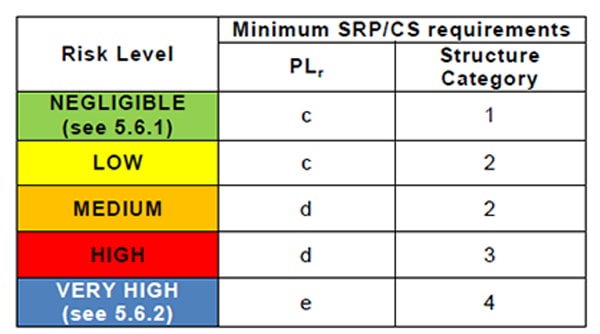
The performance level required of your safety controls is shown in the table below.
The next step is to put together an idea if what your controls might look like. A big part of this step is to review what the different architecture categories look like. What is your input device? What kind of monitoring will you have? What type of logic will the system be using? This diagram compares the different parts of an architecture with the different category levels:
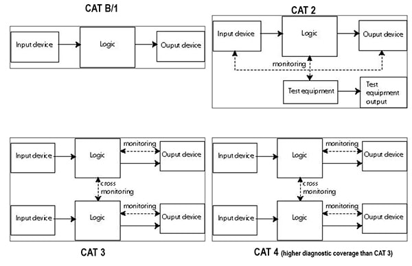
The above conceptual diagram comes from the standard. In the Cat 3 and 4 structure, you can see that there are two channels – Input device, through logic, to the output device. Keep in mind most quality components on the market incorporate the two channels in one device. Typically, machine safety control circuits are Cat 3 or Cat 4.
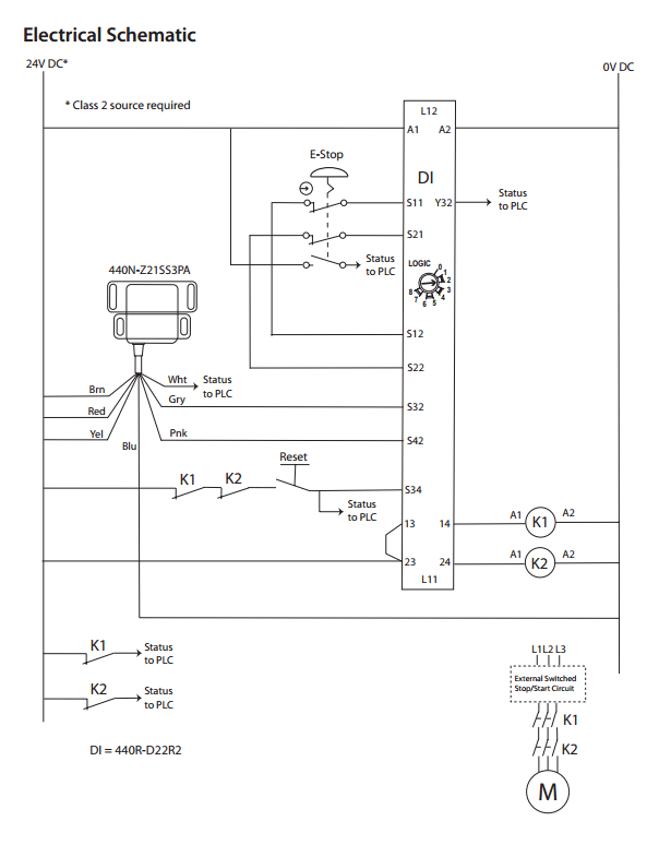
For comparison here is a wiring diagram. This comes from Rockwell Automation, on their pre-engineered safety functions webpage. This circuit meets the highest levels of Ple/Cat 4. In the electrical schematic, the 440N is a door interlock which is tied into the 440R safety relay and an e-stop. The circuit has a dual channel on BOTH inputs, with monitoring on the channels for immediate notification if a fault occurs. The safety relay is self-monitoring. And the circuit has dual output contactors. In case one the welds closed; no restart is possible until the issue is fixed.
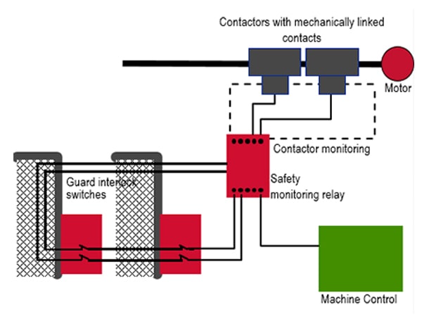
Here is an example diagram. It shows two door interlocks wired in series. Note the dual channels from the input device into the safety relay. Notice also that the safety relay is monitoring the status of the output contactors.
Let’s assume you have an application in mind that you are ready to tackle. Let’s assume you have read the above content and have a basic understanding of how to determine the required performance level. Now you need to select and specify components with an acceptable MTTFd rating and ensure you are monitoring the circuit correctly.
This can be done via the methods described in the Standards via manual calculations. Or this can be accomplished through software tools. These tools automate many of the longhand calculations and make the task relatively easy:
Hopefully, this post answered a lot of your questions about how to set up your safety control system. I covered lots of ground in this post. There’s a bit to it, but it’s really not that hard when you dig in. If you find yourself with questions we haven’t addressed here, feel free to reach out to an Automation Specialist.