
Blog > Automation > Tuningless Servo Drives
Tuningless Servo Drives
8/28/18 | Andy Lussier, Rexel Technical Consultant
Blog > Automation > Tuningless Servo Drives
8/28/18 | Andy Lussier, Rexel Technical Consultant
With the popularity of servos being used in numerous applications today, the need for tools to shorten the commissioning time of these servo systems has created some great features. What used to take hours is now greatly reduced and we have evolved to systems that have "tuningless" and adaptive tuning features. Yes, I said tuningless. This post will delve into the what and how of tuningless servo drives.
Before we get into tuningless, let’s get a standard definition of tuning:
Closed-loop servo systems require settings for the control loop gain and filter values to make sure that the load accurately follows the desired input-command signal. The process of adjusting and refining the gain and filter configuration is called tuning.
Motion Controllers, at the planner level, maintain control of move profiles (position, velocity, acceleration, deceleration) based on the application requirements. Ultimately, the Motion Controller generates a commanded motion path based on the motion program. They allow the user to do everything from jogging, electronic gearing and point to point moves to complex motion profiles like electronic camming, multi-axis coordinated motion, and even kinematic functions.
Servo Drives take these coarse move trajectory points generated by the Motion Controller and interpolate them into smooth motion. This path (Commanded position/velocity) is continually compared to the Actual position/velocity of the system. Feedback from the motor is used to calculate (Commanded Position/Velocity – Actual Position/velocity) and generates an Error Command which corrects the error and assures accuracy and repeatability. This is referred to as a “Closed Loop” system and is what makes a servo a servo.
A simple representation of a “Closed Loop Position Servo” or “Servo” system block diagram is shown below. The Servo loop below (also known as a Nested PI Servo Loop) can be compared to a series of dominos.
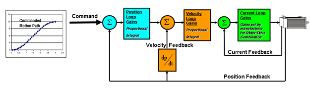
In a Nested PI Servo Loop, the position loop is used to detect the position error. Its output command, based on the error, is sent to the velocity loop which commands the motor to speed up or slow down to eliminate the error.
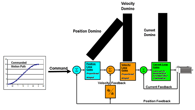
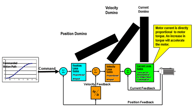
To speed up or slow down the motor and correct the position error, the velocity loop commands the current loop to produce a change in current creating more/less torque to accelerate or decelerate the motor/load.
Servo Tuning is the process of adjusting the gains of each loop to match the responsiveness of the motion control to the machine dynamics and application requirements for repeatability and/or accuracy. A very important consideration when sizing a servo motor and drive is knowing the system inertia to help optimize the tuning process. If your inertia ratio between the motor and the load is too great, you may have a hard time tuning your system for repeatable and smooth motion.
A servo does not work without error between the command and the actual. This is what makes a servo a servo, its ability to respond to errors. The servo loop bandwidth is how fast the ability to respond to the error is. This bandwidth can be adjusted by the user for the desired system performance. If you’re too responsive, you have unstable system. Not responsive enough and you may not get where you’re going.
In the past, it was up to the user to manually adjust these gains for the desired response based on the application requirements. While most manufacturers have ‘autotune’ features, the autotune gains would typically get you in the ballpark for performance. What most overlook when manually adjusting gains in the individual loops is that, depending on the application, how those loops interact can be dramatically affected. If you didn’t spend the time to understand the block diagram of these loops, you may create a tuning nightmare for yourself.
With the Tuningless feature support in Kinetix® 5700 and Kinetix® 5500 servo drives, the user can have their servo system up and running in dramatically less time. Load Observer allows for compensation of disturbances in the load as an axis is moving as well as unknown or time-varying load inertias in the system. Since it is adaptive, as your system wears mechanically and the friction load changes or your load changes, retuning is no longer required. This is especially beneficial if your machine runs products of varying weights or if you have an unbalanced load. Load Observer provides robustness and stability to your system and increases reliability. No more following error faults here… Ideally, Load Observer simplifies the tuning process for most applications.
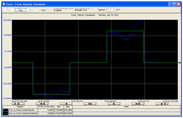
The trend below is of a system with a high inertia mismatch (1:110) where both gravity and varying load inertia affects servo loop response. This could be a rotary knife application or a crank and in either case, our load is unbalanced. The green plot is the command velocity, and the blue plot is the actual velocity.
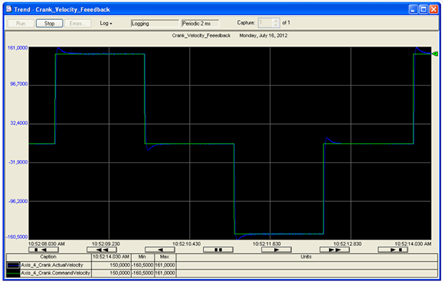
Now with Load Observer turned on we’ll see a dramatic difference in the performance of this axis.
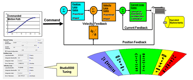
When a Kinetix5500 or Kinetix5700 are configured in a Studio5000® application, the user can elect to use Load Observer. After reviewing our example, why wouldn’t you?
A consideration of whether you elect to use Load Observer, autotuning, or manual tuning is how stiff your system is mechanically. Mechanical compliance or lack of mechanical stiffness creates tuning nightmares… PERIOD. Think of it like this, which one would you want your load coupled to, a rubber band or a solid shaft? Backlash in a system may also create tuning challenges in addition to potential repeatability issues with desired moves as it is a form of compliance.
While Load Observer is a great feature and we have seen the effects of what it can do in our example, it cannot solve mechanical issues in your servo application. Proper selection of couplings, belts, actuators, and even gearboxes need to be considered at the design stage of your project.
Belt style actuators and belt & pulley transmissions are common in servo applications. When using belts, always go for the steel-reinforced or poly chain ones as they are stiffer/less compliant. Stay away from the Kevlar and nylon core belts as you may as well just use that rubber band in the top drawer of your desk. If you use Kevlar or nylon core belts, system stability and tuning can be improved by using gearboxes between the motor and the belt style actuator.
Couplings: The stiffer the better. Be sure to use servo rated units. Rigid couplings are best however are less forgiving with angular misalignment (angular, parallel, axial). Beam and Bellow style are good too but be sure you look at the stiffness rating. Jaw or Spider style can present issues if the elastomer spiders are not stiff enough. Application note… angular misalignment can add additional loading to your system and potentially cause coupling or shaft failures so pay attention to those coupling specifications.
Gearboxes: When in doubt, use servo rated gearboxes as they are a lower backlash and higher efficiency over the lower end inexpensive “rock crushers.” The “rock crushers” are typically higher friction, less efficient and have a higher amount of backlash than servo rated gearboxes. Planetary gearboxes provide higher torsional rigidity and accuracy by having multiple pinion gear contact points. For right-angle configurations, spiral bevel gears have higher contact ratios for higher accuracy and rigidity and hypoid gears provide higher ratios in a single gear pass, without sacrificing rigidity. In the end, these planetary, spiral bevel and hypoid style gearheads are designed for servo applications, so you can’t really go wrong.
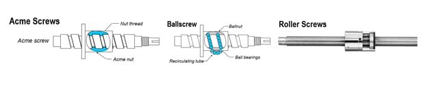
Screw actuators: Consider the type (ACME, ball, roller screw) in your design as your selection will have an impact on the reflected load that the motor sees. Each has things to consider with respect to tuning. ACME screw by nature are high friction (low efficiency) so if it is not accounted for in your sizing, it may add an additional load that your motor sees (another plug for Load Observer). Ballscrews are typically lower friction however require frequent lubrication. If left unmaintained, the frictional load will have an impact on your tuning and system performance. Roller Screws are fairly rigid and if sized properly and mated ‘rigidly’ to your motor, will provide a robust and stable system.
While Load Observer will allow you to compensate for oversights in design and can greatly reduce your servo commissioning time, remember… the laws of physics will always prevail so take the time to size your system with consideration of not only the load that you are moving but the move profile you are trying to achieve. This will make your life much easier when it comes time to tune and commission your system. Moving 200lbs 30 inches in 15 seconds has different demands on a motor than moving 200lbs 30 inches in 1 second.
Questions? Ready to learn more? Contact us today!