Blog > Safety > Improve Efficiency and Streamline Machine Safety with GuardLink™
Improve Efficiency and Streamline Machine Safety with GuardLink™
3/14/23 | Tom Hopkins, Automation Specialist

Blog > Safety > Improve Efficiency and Streamline Machine Safety with GuardLink™
3/14/23 | Tom Hopkins, Automation Specialist
Let’s say you are adding, or upgrading, a safety system on an existing machine. There are many safety inputs required: door switches (some locking), e-stops, some light curtains, a robot cell with an area laser scanner, and a conveyor with cable pull switches. Some of the hazards on the machine are serious and you want the ability to reach Performance Level “e” / Cat 4*. You also want the PLC to have status indication of each device to quickly identify the source of the safety demand. Identifying the location of the triggering device quickly will ensure no delay in addressing the issue and resetting the machine. Therefore, production levels will then stay at a high level and keep the plant manager happy.
From your experience in the past, the above requirement for diagnostics means you’ll need to run home run lines to each safety input device. That’s a lot of work and uses up a lot of valuable input terminals. If you were to connect safety devices in series, you would save valuable safety inputs, but risk ”fault masking.”** i.e., you won’t get to Performance Level “e” by wiring in series.
GuardLink allows the connection of ALL your safety input devices on a series line. Because there is built-in intelligence to the system you can get to Performance Level “e” even with all devices wired in series. The system allows you to know exactly which device was triggered. And you can lock/unlock individual devices in the line if you have locking door switches.
All types of safety devices can be placed in series. This means all the e-stops, the door switches (locking or not), light curtains, and cable pull switches in your application can be on one line. You can series wire up to 32 devices per trunk line, and the line can be up to 1,000 meters long.
All connections are quick connect M12 micro, so there’s no concern about mis-wiring and troubleshooting during implementation. A trunk line is made up of M12 patch cables, and each device is teed off that trunk with what is called a ”Smart – T.” This makes for fast, trouble-free implementation.
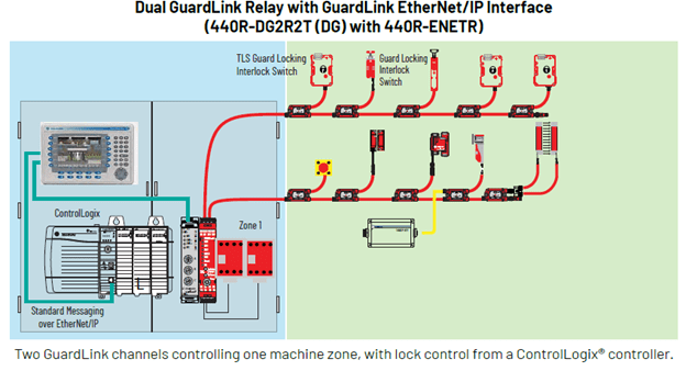
For a simple application with one safety zone, GuardLink uses a dedicated safety relay: 440R-DG2R2T (often called the DG relay). You can series wire up to 64 devices (32 devices on two trunk lines). If the machine is long, the two separate lines can reach in opposite directions from the safety relay, allowing a span up to 2,000 meters.
The DG safety relay can stand alone to handle all safety functions without the need of a safety-rated PLC. When there is a demand on the safety system, the relay’s auxiliary contact can send a signal to the standard control PLC to make it aware of the triggered condition. To see the status of each input devices, or lock/unlock door switches, you add an ethernet communications module. See the graphic below for better understanding (Blue shaded are in-panel devices and green are on-machine).

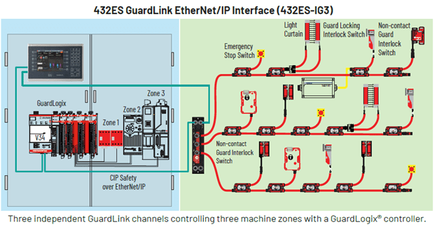
The second generation of GuardLink allows up to three safety zones off one module. The 432ES-IG3 module is a distributed IO device that mounts on the machine. This module communicates CIP Safety over Ethernet to a GuardLogix safety processor. All the same rules apply to the input trunk lines — up to 32 devices per trunk line and a max of 1,000 meters per trunk line.
Click here to download the GuardLink 2.0 brochure.
See another graphic below for better understanding (Blue shaded are in-panel devices and green are on-machine).


Tom has worked in the world of automation for 20+ years and is certified by TUV Rheinland as a functional safety technician (#319/15). Our experts are standing by to answer your GuardLink questions and assist with installation. Contact us today!
GuardLink images are © Rockwell Automation
Footnotes
*Performance Level ‘e’. This is the highest level of machine safety control, reference the ISO 13849 machine safety control standard
**Fault masking - In a series circuit when a safety logic device identifies a fault in one safety switch. This fault could be reset by operating other safety switches in the series. This then leaves the original fault in place and undetected.