
Blog > Automation > How to Size a Servo Axis
How to Size a Servo Axis
5/13/20 | Chris Williams, Rexel Technical Consultant
Part 1: What Information do I Need for Sizing?
In this two-part series (read part two here), we will discuss what information you need before you can size a motion system and then what values and calculation you need to know to select your components. In part one, we’ll examine how and where to get all the information you need to size a servo axis.
Sizing Servo Systems
As a motion control specialist, one of the most frequent tasks I am faced with is to size servo systems. For most applications, this is a pretty straight forward task but does take a good amount of preparation and understanding to make it that way. Before any engineer can start to size a servo axis, they must gather all the necessary information. The easiest way of going about this is to start from the load and work back to the actuator. This is especially important when sizing multiaxis gantries as the axes closer to the load need to be sized first so the load for the later axes can be accurate.

Using Modeling Software
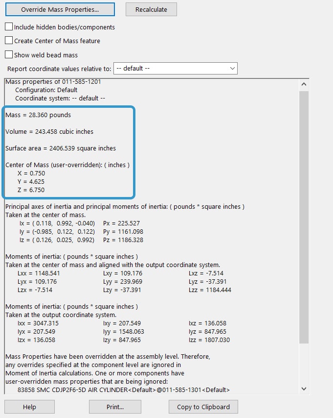
When sizing a linear axis, an engineer needs to know the mass and the center of mass (COM) of the load relative to the actuator’s carriage. This value can usually be found in the solid modeling software used to build the system. An example of where you would find this information in SOLIDWORKS® is shown below. In addition to this value, we need to know the move distances, speeds, dwells, and cycle times to properly size the motor and actuator. These items can be nicely summed up in a system timing chart. This is a good visual way to layout the process of the system which translates well into the sizing software when building the motion profile. More advanced properties such as jerk rates may be needed when handling delicate materials and can be reviewed on a per-application basis.
Sizing a Rotary System
When sizing a rotary system, instead of knowing the mass and COM, we need to know the rotary inertia around the axis of rotation, this is especially important for rotary axes so we can keep the inertia ratio to a proper value. This value can also be found in the mass properties of the modeling software. The engineer designing the models does need to be careful to set up the proper coordinate axis to make sure the inertia value will be correct. In addition to the inertia, a timing chart with the same information as the linear axis is necessary for sizing a rotary system.
Determining Accuracy Requirements
For both rotary and linear systems, the engineer needs to determine the accuracy requirements for the system. For linear mechanics, this will be most commonly the repeatability of the actuator but also the accuracy, straightness, and flatness. For rotary mechanics, the backlash of the gearbox and couplings need to be considered.
System Integration Data
The final information needed when you size a servo axis is related to the overall integration with the larger system. You will need information on cable lengths and voltages to integrate the electrical system, and you need the controller model to determine what type of drive can be used and what safety system. Typically, the drive and motion control requirement will dictate the required controller to be a motion controller (ex. -ERM CompactLogix controllers).
This is not a complete list of parameters that need to be considered; different factors can arise in different applications such as temperature, vacuum, hazardous environments, and more. In part two, the next step to size a servo axis is reviewing the actual calculations for selecting actuators, motors, and drives.
We Can Help You Size a Servo Axis
You don’t have to go it alone. Our motion control experts are here to walk you through the process and make recommendations based on your specific needs. We can even design an end-to-end solution. Contact us today!