Blog > Automation > Calculations for Sizing a Servo Axis
Calculations for Sizing a Servo Axis
9/15/20 | Chris Williams, Rexel Technical Consultant
Building the Motion Profile
In part one, we walked you through the information you need before sizing a servo axis. Once you’ve gathered all the information on your system, you need to put the movements into a motion profile. In this blog, we’ll go through calculations for sizing a servo axis. We will use a simple application for our example. Let’s say we have a 50 kg load that we want to move 500mm in one second, and we will do this every two seconds. The easiest way to calculate all the information for our profile is to enter it into a program like the Rockwell Automation® Motion Analyzer.
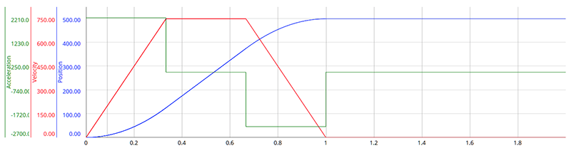
You can also calculate by hand with a few equations, if you so choose, or if you want to understand the math behind the program. To size the rest of the system by hand, we would need the maximum velocity, acceleration, and force/torque. For this, we will also assume a standard trapezoidal move profile.
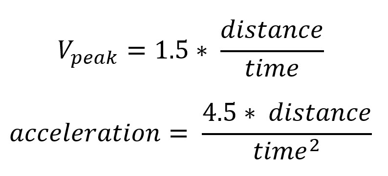
FOR A LINEAR APPLICATION:

FOR A ROTARY APPLICATION:

Sizing/Selecting Mechanics
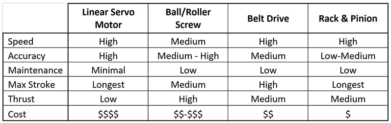
OVERVIEW
SPEED
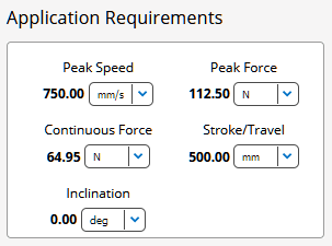
For our example application, we have a peak speed of 750 mm/sec. This means that we can use any of the options shown in the overview table. Typically, screws are the most limited, with peak speeds being around 1200 mm/sec, but some can go faster than that. Linear servos, belt drives, and rack & pinion systems can typically all achieve multiple meter/sec speeds without issue.
Usually, belt and screw actuators will be the best starting point, with screws being the most common option unless longer strokes or higher speeds are required. The reason for this is belt actuators typically need a gearbox to compensate for the system inertia while the screw actuators do not. We will touch on this more later.
THRUST FORCE
For our application, we do not have any applied force, so the only force comes from the acceleration. Using the earlier equation, the force required works out to 112.5 N.
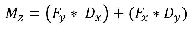
MOMENT LOADING
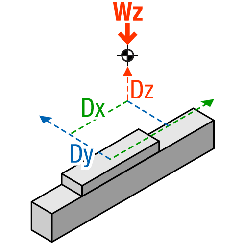
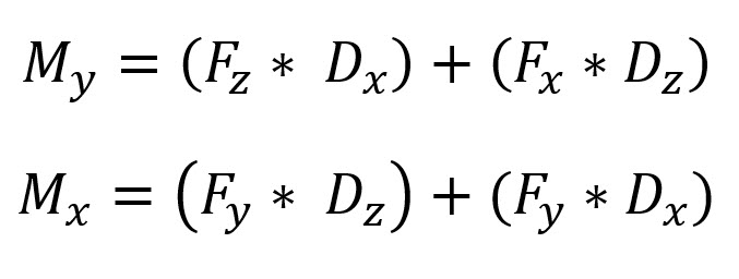
For this application, we will say the center of mass of the load is located off the carriage by 100mm in the Y direction and 50mm in the Z direction. To quickly calculate the moment loading on the actuator, we can use the following:
Note that most actuators will be the weakest in the Mx rating. This loading will give the bearing system the least amount of mechanical advantage to support the load. To help compensate for this, we need to select an actuator with a wide base to support the overhung load better.
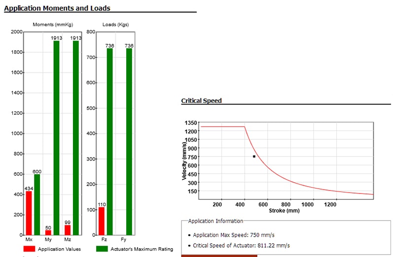
ACTUATOR SELECTION
If we use a sizing tool like that provided by Tolomatic®, we will get the values for the speed, forces, and moments based on the motion profile we enter. Tolomatic’s sizing tool will then use this information to provide a list of recommended actuators. Once an actuator is selected, you can see how much of the actuator’s capacity is used by the current application.
Sizing/Selecting Motors
SPEED
If we are working on a rotary application, then we already know the speed that the motor will need to be capable of. If we are working on a linear application, then we will need to make some more calculations to get our data for rotary values to select the motor. Luckily, it is simple to convert from a linear to rotary speed.
FOR A SCREW SYSTEM:
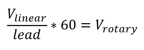
FOR A BELT SYSTEM:
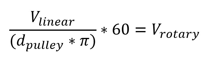
Both equations will give you the required peak motor speed in revolutions per minute (RPMs). For our example application, we can also get this information from our Motion Analyzer software. If we choose and actuator with a 10mm screw, we will need a motor capable of at least 4500 RPMs.
TORQUE
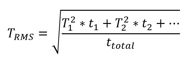
When calculating the required toque, we will have to focus on both the peak torque as well and the continuous (RMS) torque. The continuous torque is calculated based on the duty cycle of the system as well as the required torque at various stages of travel.
CONTINUOUS TORQUE:
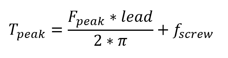
FOR THE PEAK TORQUE OF A SCREW SYSTEM:
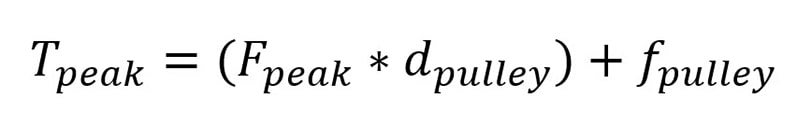
FOR THE PEAK TORQUE OF A BELT SYSTEM:
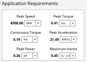
For our example system, a VPL-B0633T-PJ12AA will work just fine and give us a comfortable safety factor.
INERTIA
Ensuring the correct inertia ratio is one of the most important parts of sizing a servo system. Even if the mechanics and motor can handle all the required speeds, forces, and torques, you will still have a hard time properly controlling the system if the inertia ratio is too high. Most of the time, when working with a screw-based system, there is enough mechanical advantage that the inertia ratio will not be an issue. With a belt-based system, you will almost always have to use a gearbox to compensate for the system inertia.
For our example application, the 10mm screw would give an inertia ratio of 4.67:1, and a 40mm pulley belt actuator would give a ratio of 673:1!
For more information on inertia ratios, please read our blog here.
Sizing/Selecting Drives
CURRENT/POWER
Once you have selected the proper motor for your application, there are a couple of ways to select the proper drive. The simplest approach is to use something like a design guide to select the recommended drive for the given motor. This will work out just fine, but depending on the application, the drive may end up oversized.
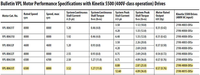
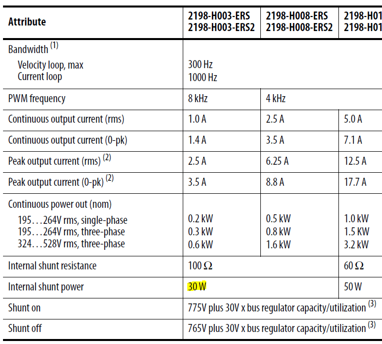
The other option is to take the data from Motion Analyzer and use that to select the drive. Based on the info below, we see that we can use the 2198-H003-ERSx servo drive. If we had used the design guide, we would be using a drive one or two sizes larger than necessary.
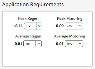
We also need to check to make sure the internal shunt will be capable of handling any regen in the system. This is another task that can be automatically handled in Motion Analyzer, but if you need to calculate it manually, we can see that the average regen comes to about 7.5W. The drive we selected is capable of handling up to 30W.
We Can Help You Size a Servo Axis
You don’t have to go it alone. Our motion control experts are here to walk you through the process and make recommendations based on your specific needs. We can even design an end-to-end solution. Contact us today!