
Blog > Automation > Torque Regulation with PowerFlex 750 Series Drives
Torque Regulation with PowerFlex 750 Series Drives
3/23/21 | Scott Savage, Rexel Technical Consultant
Blog > Automation > Torque Regulation with PowerFlex 750 Series Drives
3/23/21 | Scott Savage, Rexel Technical Consultant
VFDs (variable frequency drives) have usually been used for speed regulation over the years; the issue comes with placing two motors on a mechanically coupled load and running both in speed regulators. Both frequency regulators in the drive tend to fight each other to be the lead drive. This can lead to overheating, poor performance, and dissatisfaction in a load sharing situation. Performance can be achieved with some simple changes to one of multiple motors.
Applications include heavy-duty loads that have a mechanical connection. You can do this by either product coupling (web handling) or mechanical coupling via a belt (conveyor) or two motors on one shaft directly coupled together.
The concept may be hard to grasp for someone who has only used VFDs as a speed regulator. Economy drives only offer the drive as frequency control, but sophisticated drives have more options, for example PowerFlex® 750 series drives. Running the drive in torque mode requires a full flux vector mode evaluating torque current (shaft) and proper motor winding management (flux) to achieve torque and speed control.
Picture two horses pulling a sleigh; one will lead, and one will follow. If both horses wish to lead, it will not work. The same with leaving both drives commonly tied together as speed regulators, it will not work; therefore, the drives must be placed in different modes of operation to operate properly.
The best hardware setup is to place an encoder (if running lower speeds for proper slip adjustment) on the torque follower to ensure the motor gets up to speed smoothly and switches over to the torque mode from the speed regulator on startup smoothly. For some applications, you can use open loop without an encoder, but it can pose some performance issues getting up to speed. Direct coupled motors may require an encoder.
This blog is to enlighten everyone on a new concept: AC drives do more than change speeds, they can do torque control and even crude positioning at higher horsepower without a servo.
Feedback Accuracies
Flux vector mode allows you to manage the torque through two separate components. The drive running in vector mode has two components that are individually controlled, shaft torque called torque current and flux current to the winding. Speed regulators do not allow this extensive control.
So now the follower drive matches the torque of the lead drive. FORCE drive control from Allen-Bradley® easily accomplishes this. The limited torque reference is passed from the lead drive to the follower drive.
There are different modes to run as a torque regulator:
You do not have to run this as a network drive, which requires a Logix processor, torque control can be achieved via an analog signal between the drives. You get better control with a PLC, it’s but not necessary. This article will concentrate on analog signals via a PLC or drive to drive.
SLAT MIN – When [P4 Commanded Torque] is algebraically less than the internal speed regulator output of the drive, the drive can automatically go from torque regulation to speed regulation (depending on certain conditions) used a lot on web applications.
SLAT MAX – When [P4 Commanded Torque] is algebraically more than the internal speed regulator output of the drive, it can automatically go from torque regulation to speed regulation (depending on certain conditions) used a lot on web applications.
The PowerFlex 750 reference manual (750-RM002) goes into a deep dive on many applications including torque control.
Parameter numbers and descriptions:
Parameter numbers and descriptions:
You must tune the drive in a speed regulation mode for autotune and inertia tune, and then switch parameter 35 to torque regulation or SLAT min/max control for the follower drive. Motor data must be entered in the drive prior to the autotune and inertia tune. Autotune will be done without the load on the motor, if you cannot release the load at time of tuning, then run a static tune (not as effective as rotate tune and has lower performance).
All tests must pass—direction test, autotune (rotate or static), and inertia tune in this order. Then place in torque mode. Please make sure both drives are rotating the same direction.
Note: After inertia tune take the total inertia value and divide in half because there are two motors hooked to the load at time of inertia tune.
Please keep in mind, this is the starting point of the torque journey. Once both motors are running, you will need to adjust certain parameters to improve performance.
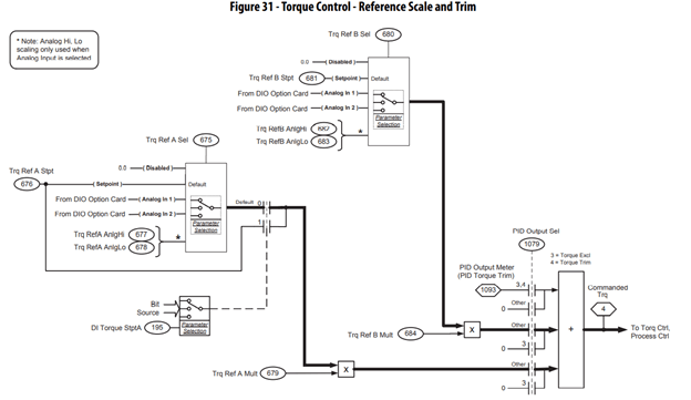
Here is an example using two torque references if the application warrants, using two analog signals. The trq ref A P[675] and trq ref B P[680] reside in the torque follower drive and would receive an analog signal from the speed regulation drive analog output. The PowerFlex 750 series is modular, so you would assign the proper port on the speed regulator as well as the torque regulator.
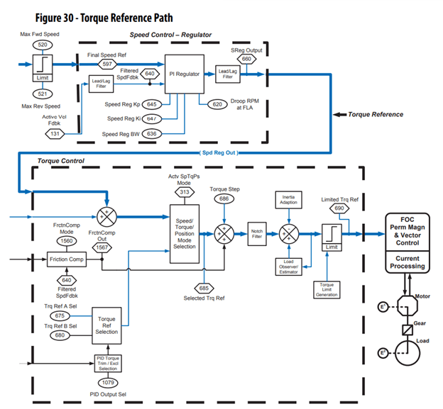
Figure 30 shows the speed regulator and the torque following drive. Please observe the parameters that influence the application results at points on the torque path. This is a great review of some of the parameters that need to be adjusted.
Let’s start with the torque regulator, the I/O module that has the analog channel 0 is in port 4 of the follower drive. Drive tuning is completed, and now we need to assign an analog input for the torque regulator to follow.
The views shown below are using Connected Component Workbench. This can be downloaded from the Product Compatibility and Download Center on the Rockwell Automation® website.
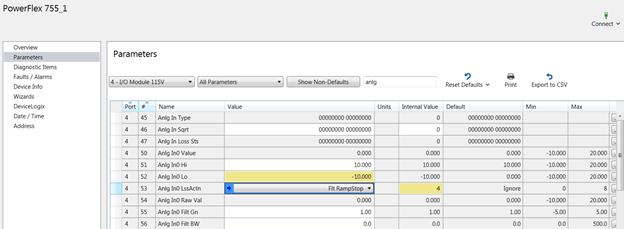
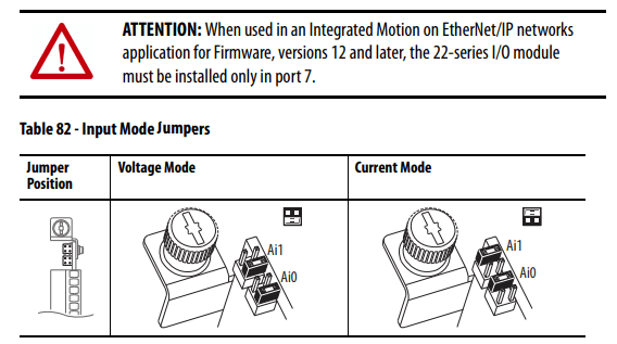
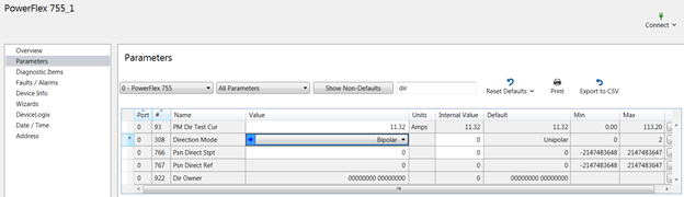
We have now set P[51] and P[52] to bipolar scaling. This will allow the drive to follow positive and negative torque levels. P[53] can be set to a variety of signal loss (LssActn), this example we will ramp to a stop. Coast is also an option if this is more beneficial. Please note, you will need to navigate to port 4 parameters to see the proper parameter set. The analog channel is in port 4 of the drive. The analog input jumpers are already set to 10V. You can check in the PowerFlex drive installation manual for proper strap positions. The jumpers are on the top of the I/O module near the screw shown facing out of drive.
The direction mode must be changed on the drive for bipolar operation; this will allow the follower to provide positive and negative torque. Now, we are in port 4, and we need to navigate to port 0, which is the main control board for the drive. Notice the port number has changed and is now “0” not port 4. Change parameter 308 in port 0 to bipolar.
Now it is time to set the follower drive to torque mode P[309].
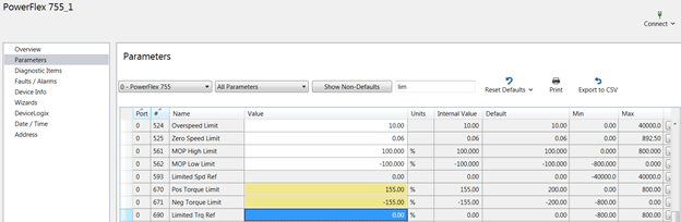
Set the torque limits and set the limits to your application. This example will be set to 155% in positive direction and -155% for negative direction. This will allow the lead drive programmed at the + 150% to control the upper and lower limits of the torque control.
Now let’s avoid any nuisance faults and adjust certain parameters to keep the drive operating.
Note: P[372] reg bus mode A is set to “frequency”
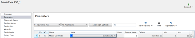
The lead drive needs to be in speed regulation mode P[309], and the preferred motor control mode P[35] is induction FV.
Performance on the lead drive may not be sufficient in a sensorless vector mode (SVC). Please note, you should turn off P[461] and P[409] discussed above in either motor control mode.
Change P[670] pos trq lim to 150% and P[671] neg trq lim to 150%. All the clamping will take place in the lead drive. The follower drive is set to 155% on both limits to allow the lead drive to set the limits.
Now you have programmed both drives, it is time to spin some motors!
If the lead drive faults, the follower will not receive a torque reference. This condition means the follower will attempt to coast to a rest.
Keep in mind, if the follower drive faults, the lead drive will carry the entire load and possibly current limit and potentially stall. The lead drive could then trip on overload. Be aware of the fault codes and make some adjustments to avoid tripping out.
Conveyors with different diameters must be scaled mathematically to achieve the same surface speeds. These can be accomplished with scaling the analog output of the lead drive or analog input of the follower drive. It should be the same ratio as the diameter differences in the rolls. This application should be run in straight up torque regulation mode, if possible.
Nip rolls follow the same procedure; the outer surfaces are different materials as well as diameters to allow enhanced grip. These rolls should be approximately the diameter ratio, and some may have more slip, depending on the materials. Web handling should be done in either SLAT min or SLAT max mode to help with acceleration and deceleration and ramp control stopping. This mode allows the drive to shift modes from torque regulation to speed regulation when necessary.
When running two motors that share the load, both should not be run in speed regulation, the motors will show signs of overheating and premature failure. If you are running an application with two speed regulators, and are experiencing motor failure, please consider this as a solution to the problem.
Would you like to know more? Do you have questions about torque regulation? Contact us today!