
Blog > Automation > Improving the Performance of Your VFD in Heavy Duty Applications
Improving the Performance of Your VFD in Heavy Duty Applications
5/18/22 | Scott Savage, Rexel Technical Consultant
Blog > Automation > Improving the Performance of Your VFD in Heavy Duty Applications
5/18/22 | Scott Savage, Rexel Technical Consultant
Here’s something that many of us ponder: Am I getting the best performance out of the VFDs (variable frequency drives)? on my heavy-duty applications? Whether you’re preparing to install a VFD or have previously installed one, wanting optimal performance is natural. This blog will address the three operation modes and when to use each mode, allowing for the best and most reliable characteristics of the drive in a variety of heavy-duty applications.
The Digital Era of Digital AC Drives
The AC drive technology now locks into the parameter selection and no longer drifts like analog DC drives of the past. The fourth industrial revolution demands reliability and consistency. Not only do modern AC drives stay consistent, but in the motor control mode, you can also program the drive with different modes. These modes can make a big difference, adding to the performance of the drive and allowing it to respond to different types of loads on the motor.
As I mentioned in my earlier post about improving the performance of pumps and fans, the feedback from the field I hear from customers is: Is it an electrical problem or is it a mechanical problem? It may be better to rethink the division of the two trades “electrical” or “mechanical,” and think of both instead. The load, which is mechanical, affects the drive. It is important to understand the actions of the load upon the drive and the dynamics it will cause. Trying to separate the two is a recipe for failure; the drive team must view the entire system from the drive to the load itself.
1) Static Tune – If the load cannot rotate while attached to the motor, this is the only alternative. The performance is limited, but it’s better than out of the box performance for your heavy-duty applications.
2) Rotate Tune – This provides optimal performance and is superior to static tuning. Your load must be released from motor shaft (SVC only).

V/Hz – Requires no autotune for the motor. The only motor data that needs to be entered is the motor amps to protect the motor from an overload situation. If motors are changed, there is no retuning of the drive. Performance is average—sluggish compared to SVC for applications with shock loading or cams.
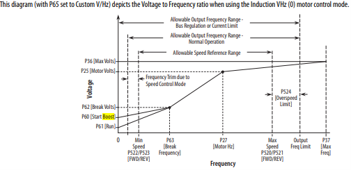
Changing the break voltage or break frequency changes the torque on acceleration. The greater the ratio of V/Hz increases the torque. This is a manual process and there is no dynamic boosting like SVC.
This is a manual process and is not dynamic like Sensorless Vector Control is.
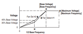
Typically, a fan curve is chosen from a choice of predetermined curves as shown above. Initial startup torque can be increased for more boost at initial startup torque if needed. The curve remains the same after an initial boost, unlike the ability to change the V/Hz ratio in a custom curve.
Large inertia loads such as induced draft fans and force air fans should be run in a custom curve, instead of a predetermined fan curve, a custom curve allows greater startup torque. SVC is also a consideration if startup torque performance needs to be improved for large inertia fans.
SVC requires the motor to be tuned before operation with a load can be achieved. If this is not done, the motor will exhibit lack of starting performance. What does this mean? This means the drive will not develop enough starting torque. The motor will stall and not break the load free. Signs of this happening are large values in amp draw, the Hz value will hover or will stay low at 4-8 Hz, and not achieving the commanded speed of the drive. To rectify these issues, stop the drive, go to the autotune parameter, and at minimum run the static tune. Rotate tune is preferred for optimum performance for your heavy-duty applications.
NOTE: All motor data must be entered prior to autotune:
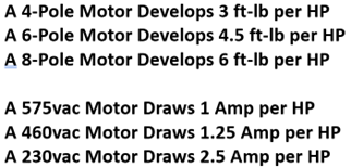
NOTE: The more poles, the greater the torque of motor and higher amp draw on the drive. Torque is congruent to amps, the more poles the more amps. Amp draw/HP shown below is for 1800RPM:
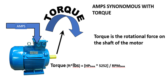
Sensorless Vector is the factory default (out of the box), and you can check the motor control parameter to ensure you are in this mode. This is used the majority of the time for heavy-duty loads listed above. Consider this for a description of what the drive is doing to the load: it dynamically adjusts the torque regulator automatically when there is a change in speed of the motor.
The motor generates counter EMF (electromagnetic force) from the motor rotor to the drive. The counter EMF is proportional to the motor speed; therefore, the drive knows the approximate speed. The sensorless vector algorithm receives the counter EMF from the motor as feedback and automatically applies more or less amps to the motor. Amps is congruent of torque, so the more amps, the greater the torque and vice versa. This was a major improvement from the older AC drives that only offered V/Hz mode. On high inertia loads, the older technology was manually adjusted with a custom V/hz curve adjusting break voltage and/or break frequency. This could be very difficult to achieve, most of the time the load could be freed without an overcurrent fault. Overcurrent faults are usually 250% of the rating of the capacity of the drive. The V/hz drives sometimes need to be oversized to achieve success. SVC changed the need to oversize the drive to the motor. Momentary boosts of 250% for 3 seconds and 150% up to one minute were achieved with SVC dynamic boosting.
Autotune
If the autotune does not complete, and the drive faults during the autotune process, please check your motor data and make sure it is correct. The drive compares the motor data to internal values that are in a range for the motor data that was entered. The results from the autotune are compared to values stored in the drive and must stay within the value range or the drive will fault during autotune.
NOTE: When the autotune is complete, the autotune value needs to return to “Ready.” If the drive autotune value is in “Calculate,” please program the parameter to “Ready” after the tuning process is complete.
If the Autotune is not at the “Ready” state it will affect the drive performance, please be aware of this if experiencing torque performance of your heavy-duty applications.
The autotune must successfully completed. If it does not, the drive must be re-tuned. A load on the shaft will fail the test in SVC, if there is a value above 30:1 reduction at the power transmission may want to perform the rotate autotune and see if it passes and does not fault.
The advent of SVC opened the ability to break the high inertia loads from a resting state vs. V/Hz. SVC can be used in most applications. It is a powerful tool to for the successful commissioning of a system. It is used in the industry over 70% of the time on many applications.
A word of caution: The gains on SVC control gains are aggressive. If the application makes the drive react too quickly to the derivative (rate of change) of the load, a mode that is less reactive might need to be used, such as V/Hz.
SVC is not used in applications that require torque regulation (load sharing between motors) or long conveyors, or vertical applications such as cranes (these are FVC). Please keep this in mind when choosing a mode of operation.
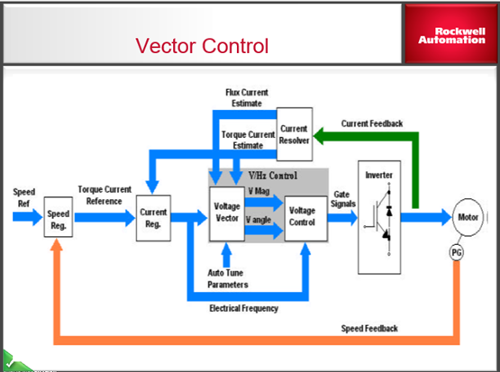
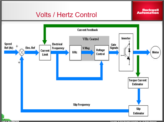
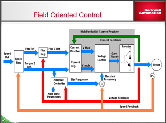
This is the algorithm for Sensorless Vector control please observe the information the current regulator forwards the flux current and torque current values as estimates to the voltage V/hz control internal in the drive. The speed feedback is the counter EMF from the motor for encoderless. Accuracies of feedback can be accomplished with encoder feedback.
Force and TotalForce typically used on roll systems
FVC (field-oriented control FORCE technology or TotalForce technology) vs. SVC or V/hz are used for the following applications:
NOTE: Running autotune is mandatory. Please follow the tuning guidelines for SVC described above. FVC with FORCE or Total technology allows tuning of the drive with the load attached to the motor unlike SVC. It allows good practice after the autotune to run the inertia test (FVC only) on the load connected also. Additional tune can be done using inertia tune on high inertia applications (strongly suggested).
FVC with FORCE technology includes the following:
To enhance performance, please consider an encoder for each of the speed and torque regulation modes listed above for FVC, especially at low grinding speeds on the motor. Remember, if you are using an induction motor and using the counter EMF as feedback instead of an encoder, it may not be enough resolution to achieve good performance at high bandwidth for heavy-duty applications.
The high bandwidth current regulator is superior to the SVC control gains can be adjusted.
Torque Regulation and Speed Regulation through the entire 2000:1 vector motor speed range
Field Oriented Control (FORCE) from Rockwell Automation® is featured in our FVC mode of PowerFlex® 755, 70, 700, 700S, and 1336FORCE series drives. It is a unique design to manage torque current on the shaft and the field of the motor separately. This is true brute vector control.
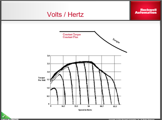
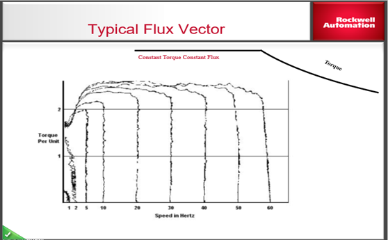
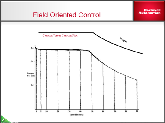
Observe the SVC diagram above, and notice it lacks the flux regulator incorporated into the FORCE technology. FORCE also has a high-bandwidth current regulator with enhanced feedback. Providing stable torque performance through the entire range in Hz shown on the torque/unit vs. Hz graph. Notice the SVC performance drastically changes at lower speeds shown on the SVC graph.
FORCE technology maintains a true regulated torque throughout the speed range and may be of interest to you as you choose your mode of performance.
TotalForce from Rockwell Automation has all the features of FORCE technology and much more including:
TotalForce also has greater bandwidth and should be considered for 700S system drive replacement.
Drives with TotalForce capabilities are:
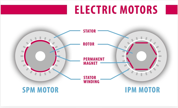
Permanent magnet motors come in two styles, this is an alternative to an induction motor. Smaller design due to the super magnets inside the motor. These motors are a great alternative if you want higher performance and higher efficiency. The rotor has a significant reduction in inertia versus an induction motor. The motors are usually in the smaller kW range.
Perhaps the biggest advantage of IPM designs, one that gives them an edge in vehicle applications like traction motors, is the high-speed performance. The power versus speed curve for SPM motors is roughly hyperbolic, rising to a region of quasi-constant power over a narrow speed range, then falling off.
Permanent magnet motors can only be operated with PowerFlex 755 drives. Compatible servo motors are listed in publications beginning with 750-PM programming manual for the PowerFlex 750 series drives, these motors and tested and approved. This document can be found on the Rockwell Automation website at Literature Library. These motors will run in FVC.
These concepts may help in many ways to a successful drive installation or even improvement on an existing operation. Remember, remember, SVC is still a V/Hz style drive, and no matter what drive you choose, consider it V/Hz with auto boost.
FORCE technology is not incorporated in the component class drives such as PowerFlex 4 or PowerFlex 5 drive class. They are speed regulators only, and they cannot execute torque control even in their FVC mode, so be careful when you choose the drive for the application. FVC does not mean it is always the patented FORCE control in the PF7 drives, we want to make that perfectly clear.
This blog was written for the intent of clarifying of choices you need to make to be successful in your drive journey, and we hope you have found this informative; it is designed to reach many levels of engineers, technicians, and electricians. Feel free to contact us with any questions that you may have. Your feedback is important to us as we team up together.