
Blog > Automation > Drive Modernization Part II: 1336 PLUS to PowerFlex 525
Drive Modernization Part II: 1336 PLUS to PowerFlex 525
3/26/19 | Scott Savage, Rexel Technical Consultant
Blog > Automation > Drive Modernization Part II: 1336 PLUS to PowerFlex 525
3/26/19 | Scott Savage, Rexel Technical Consultant
This post is the second in a series of drive modernization and migration blogs, helping you find the right drive to replace the legacy drive that has served you well. Other titles in this series include:
- Drive Modernization Part I 1336 PLUS™ to PowerFlex 750
- Drive Modernization Part III 1305 to PowerFlex 525
- Drive Modernization Part IV PowerFlex 70 to PowerFlex 525
- Drive Modernization Part V PowerFlex 700 To PowerFlex 750
- Drive Modernization Part VI PowerFlex 40 to PowerFlex 525
- Drive Modernization Part VII PowerFlex 4 to PowerFlex 523
In a previous post, I looked at converting legacy drives. Legacy drives are in every nook and cranny of our manufacturing facilities. Since the early 1990s, companies have invested in AC drive technology. The applications for AC drives are diverse. Saving energy, matching speeds on lines, and load sharing are just a few places where it makes sense to use drives. Often these drives operate till they fail. Unfortunately, most electrical departments are not prepared for when such an event occurs.

This part of my modernization blog series looks at a migration strategy for the 1336 PLUS and 1336 PLUS II drives that are 30 HP normal duty and below at 480VAC levels as well as 15 HP and below for 230VAC levels. If you are above 30 HP, please go to the blog “How do I convert from a legacy Drive?”.
- Be prepared to change over the drive efficiently when your old 1336 PLUS drive shows no sign of recovery. Being proficient and prepared when this happens will save hours of time.
- Save your 1336 PLUS program as soon as possible with DriveTools™ software
- Make sure you have an accurate schematic and that the wires are labeled
- Download the 1336S-UM001-EN-P(1336 PLUS) or 1336F-UM002-EN-P(1336 PLUS II) user manual
- Purchase a 1203-USB drive cable to retrieve and download drive parameters
- Prepare a CCW file by correlating the old DriveTools parameters to the new Connected Component Workbench parameters for new PowerFlex® drive
- First, wire up the three phase to the new drive. L1, L2, and L3 are the incoming AC power. T1, T2, and T3 are the motor leads
- Next, determine the control voltage of the drive. This will be located on the drive as an additional control board:
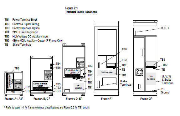
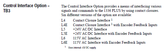
Note: The PowerFlex 525 drive has 24VDC control voltage. If you have an L6 card it will require interposing relays.
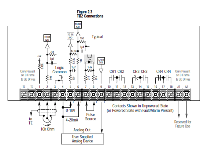
(Analog signals and relay outputs.)
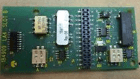
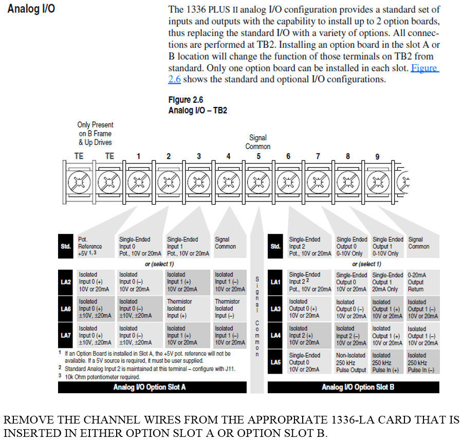
The 1336 PLUS does not have isolated analog inputs, they were a feature added in the 1336 PLUS II. Small add-in modules were added to the main control board to provide these isolated inputs and outputs. The 1336F-LA1 through 1336F-LA7 add-in modules mount with one-time mounting barbs to the main board; on smaller frames they can be behind the snap-in HIM. If you remove the HIM, you will find the modules. They look like the image above.
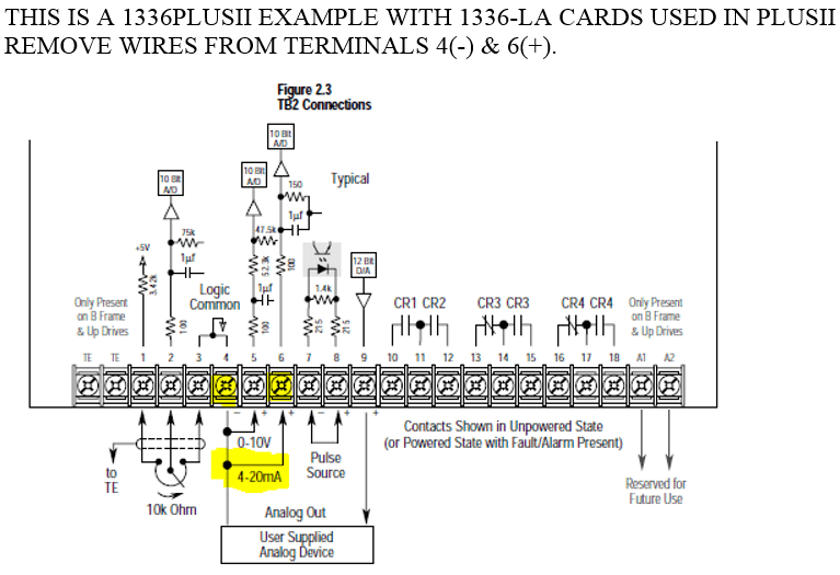
Document all the wiring to the analog I/O and relay outputs for the PowerFlex 525 drive replacement.
- Take a photograph or find some other way to document the wires going into TB2
- Plan your strategy to wire new points to the PowerFlex 525 I/O terminal strip
- Analog scaling in the PowerFlex 525 drive should not have to be adjusted to the settings in the 1336 PLUS or 1336 PLUS II
- If you are using a potentiometer for speed, the 10K pot is the same one used for the PowerFlex 525 drive
If you are using a potentiometer for speed, the 10K pot is the same one used for the PowerFlex 525 drive
Note: PowerFlex 525 drive only has one relay output. If the process requires more relays, please consider the PowerFlex 750 series drive.
If there is one takeaway for this blog, let it be this one point as you transition from the 1336 PLUS to PowerFlex 525 drive:
- Know the input mode of the 1336 PLUS or 1336 PLUS II drive
- It will tell you if you have two-wire or three-wire control
This parameter is in the setup folder on the 1336 drive. Here is the navigation map and keystrokes to get to the input mode parameter:
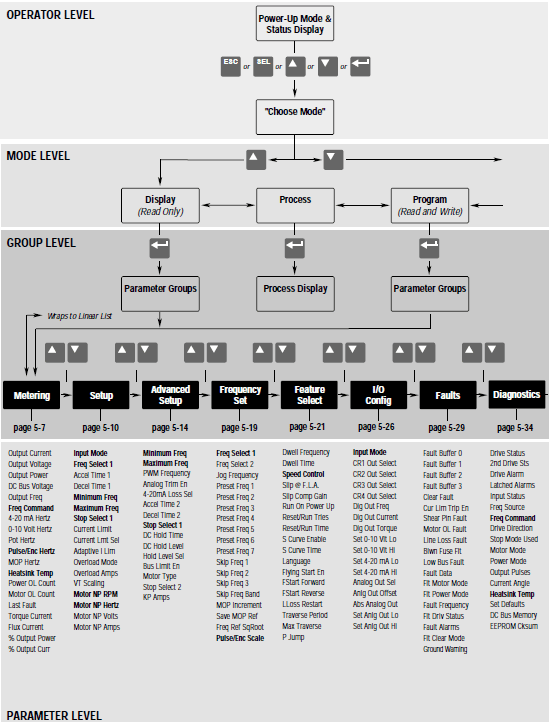
Go to the input mode parameter and observe the value. It will be numeric if it is a 1336 PLUS, and it will be two wire or three wire if it is a 1336 PLUS II. Below are the different configurations for TB3 digital input card. Here are the charts for the 1336 PLUS drive first generation:
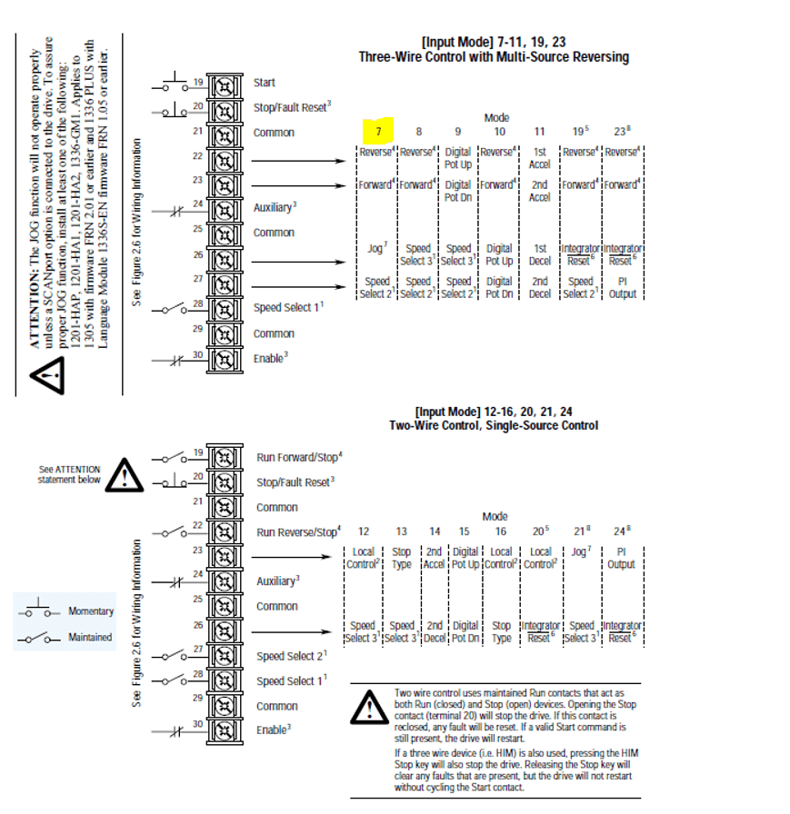
Please note, the input node numeric values and how they equate to two-wire and three-wire control. You will need to know when you wire the PowerFlex 525 drive. Input Mode 7 for the 1336 PLUS highlighted above is three-wire control. It is bipolar, meaning it can run in forward or in reverse.
- RUN, RUN FWD, RUN REV
- (OPEN THE RUN CIRCUIT)
- START (MOMENTARY)
- STOP (MOMENTARY)
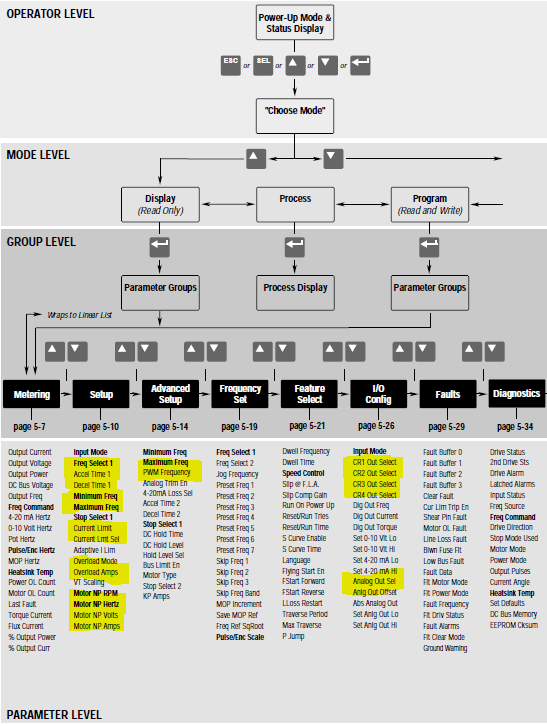
The highlighted parameters are the minimal parameters to check with DriveTools software or keypad. Above is the map and keystrokes to retrieve this information.
- Number of digital inputs and their function (TB3)
- Number of digital outputs and their function (TB2)
- Number of analog inputs and their function (TB2)
- Number of analog outputs (TB2)
- Two-wire or three-wire control, confirm which
- Full-load amps of motor
- RPM of motor
- PWM frequency set for 2 KHZ
- Set accel and decel time
- Check and set maximum freq and minimum freq
- Document speed reference and set PowerFlex 525 drive to the same wiring and programming
Now that you have all the information needed to program the PowerFlex 525 drive, you know all your wiring points and have extracted all the parameters from the 1336 PLUS with DriveTools software (downloaded from Rockwell’s PCDC download center at rockwellautomation.com).
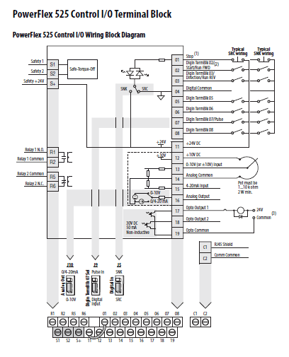
- Leave the yellow factory jumper in between terminals one and 11
- Wire the run signal to terminal two
- Wire the source voltage wire for run signal to terminal 11(24VDC)
- Press the green start button and start drive turn potentiometer on drive faceplate and change speed after starting
- Using the integral HIM or software change, 46 to a value of “two DigIN TermBlk.” Now, start the drive from the remote start station away from the drive. Change the speed from the
potentiometer on the keypad
- Remove the yellow factory jumper in between terminals one and 11
- Install stop wire to terminal one (normally closed momentary)
- Install start wire to terminal two (normally open momentary)
- Program T063 to “0” to disable input
Congratulations! You have the drive starting and stopping correctly!
Note: You can only start the drive from one location. To start someplace else, you need to point Parameter 46 to another location.
- Set parameter 47 to point to where the speed reference is coming from its proper location
- Check scaling of signal if you have a minimum speed required to run at adjust parameter 43 or adjust minimum frequency
- Remove signal to drive and make sure it faults out
- Stop button is the reset for the fault
- Analog input 4-20MA; 15(+) and 14(com)
- Analog input 0-10VDC; 13(+) and 14(com)
- Parameter 88 is set to “0” for output frequency change if necessary
- Jumper J10 is factory default 0-10VDC change to upward position for 4-20MA
- Relay outputs
- These are dry contacts AC or DC voltage can be used
- Default relay one is faulted
- Default relay two is drive running
- Connected Components Workbench
- 9328-S001K-EN
Please consider using CCW software. It’s free, and you can use the Ethernet port on the drive for fast access to the drive.
The PowerFlex 525 drive is an affordable modernization path from the 1336 PLUS drive. Please keep in mind, this is a V/hz drive with sensorless vector control (autoboost without an encoder). This is not a drive used for torque control applications; this is strictly a velocity regulator. This was exactly what the 1336 PLUS and 1336 PLUS II were, frequency drives. If you have a 1336 impact drive, please consider the PowerFlex 750.
If drive modernization seems like something you don’t want to try to do on your own, please contact us today! Our team has the expertise to install the drive for you.
All the figures and images in this post are © Rockwell Automation®