
Blog > Automation > Drive Modernization Part IV: PowerFlex 70 to PowerFlex 525
Drive Modernization Part IV: PowerFlex 70 to PowerFlex 525
7/21/20 | Scott Savage, Rexel Technical Consultant
Blog > Automation > Drive Modernization Part IV: PowerFlex 70 to PowerFlex 525
7/21/20 | Scott Savage, Rexel Technical Consultant
This post is the fourth in a series of drive migration blogs, migrate a PowerFlex 70 to PowerFlex 525 drive. Other titles in this series include:
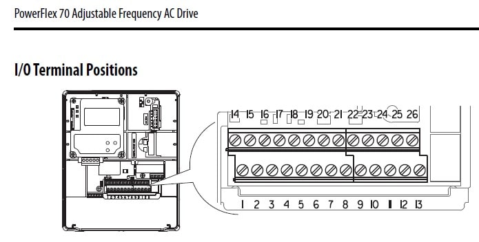
The very first PowerFlex® drive was the PowerFlex 70 drive, released at the turn of the century. The drives were still a flat and wide form factor, developed prior to the bookshelf style drives that Rockwell Automation® would later build called PowerFlex 700 drives. If you’ve been using the same PowerFlex drive for over 20 years, it may be time to consider upgrading your PowerFlex 70 to PowerFlex 525 drive. This post will give you the instructions you need.
The PowerFlex 70 drive was the advent of some new features from Rockwell Automation®:
Flux vector capabilities were added in generation 2
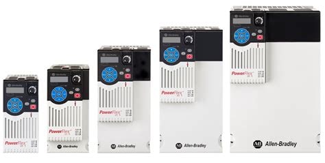
As time progressed, there was a large demand for a more cost-effective replacement drive that would satisfy the speed regulation market. This drive started development offshore, providing networking and hard-wired solutions for control. It was the PowerFlex 520 series and came at three tier levels:
For this blog, we will concentrate on programming the PowerFlex 525 drive. For simplification, please keep in mind that listed above from top to bottom are the basic drive (PowerFlex 523) to the sophisticated drive (PowerFlex 527). Let’s start with the wiring of the PowerFlex 70 drive in comparison to the PowerFlex 525 drive.
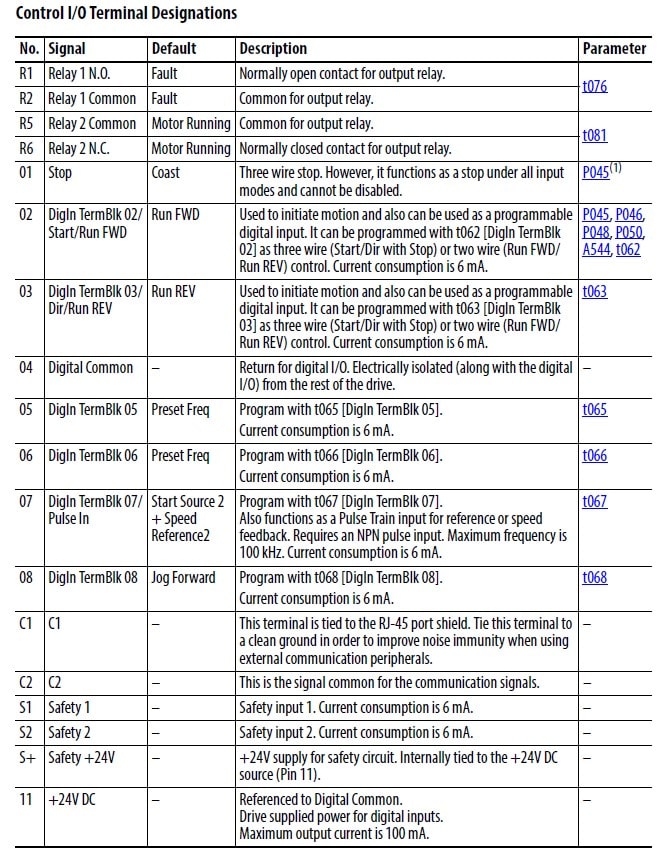
Please keep in mind, both drives are 24VDC for the inputs on the control terminal strip of the drive. The outputs provided can be electromechanical (isolated mechanical contacts that open and close) or open collector solid-state outputs (100 mA range max capacity).
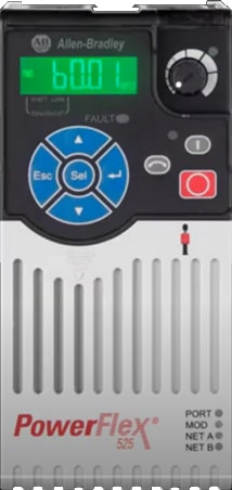
The display shows a letter followed by a number. The letter is a folder letter, and the number is the parameter number. Here are the following critical displays letters to be aware of for basic use:
(Programmable terminals 3, 5, 6)
There are more folders available. Please refer to the user manual for PowerFlex 525 drive for more details (520-UM001-EN-P), found in the Literature Library on the Rockwell Automation website.
Also, please feel free to check the YouTube video from Rockwell Automation on keypad operation.
The PowerFlex 525 drive is configurable for both “sourcing” (positive switching to input) or “sinking” (negative switching to input). The PowerFlex 70 drive used sourcing inputs so all we will discuss in the article are the sourcing style. If you do have a PowerFlex 70 system you are converting over, and it is on external 24VDC, please keep in mind the digital input common needs to tie to the drive input common for the inputs to operate properly on the PowerFlex 525 drive. (Jumper on terminal 7&8)
PowerFlex 70 Two-Wire Control – “RUN FORWARD” “RUN REVERSE”
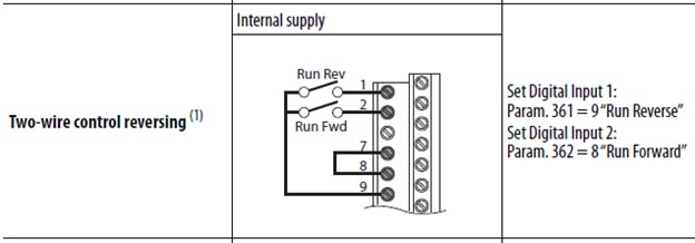
Above is the example from the 20A-IN009-EN-P Installation Manual showing a maintained switch symbol for a forward-reverse application on a PowerFlex 70 drive terminal strip. Two-wire nomenclature is “run” when described in all of Rockwell Automation’s manuals.
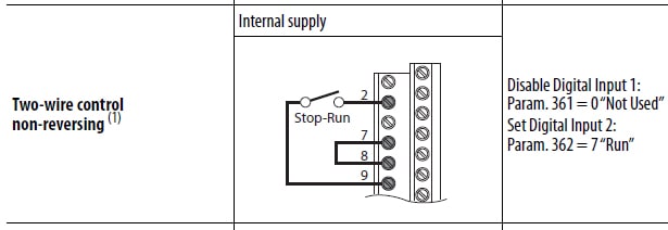
PowerFlex 525 Drive Two-Wire Control – “RUN FORWARD” “RUN REVERSE”
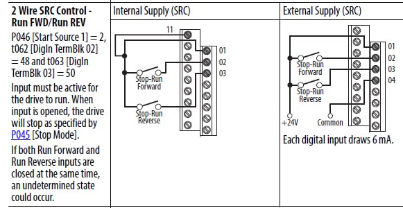
Terminal 11 is the 24VDC supply that was terminal 9 on the PowerFlex 70 drive to supply internal positive voltage to the input.
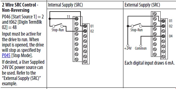
PowerFlex 70 Two-Wire Control – “RUN FORWARD”
Example of two wire non-reversing application using PowerFlex 70 drive terminal strip
PowerFlex 525 Drive Two-Wire Control – “RUN FORWARD”
PowerFlex 70 Drive Three-Wire Control – “START” “STOP”
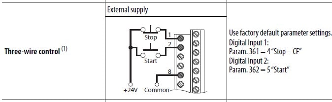
Above is an example of momentary symbols for pushbuttons used for three-wire control on PowerFlex drive 70 terminal strip EXAMPLE OF EXTERNAL SUPPLY FOR 24VDC ON PowerFlex 70.
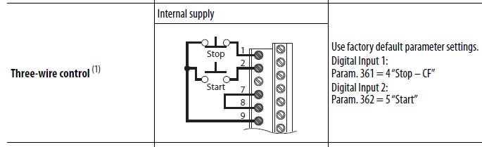
Please note, the commons must be tied together for proper operation.
PowerFlex 525 Drive Three-Wire Control – “START” “STOP”
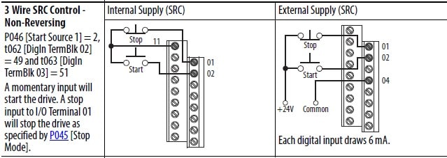
Above is an example of momentary symbols for pushbuttons used for three wire control on the PowerFlex 525 drive terminal strip.
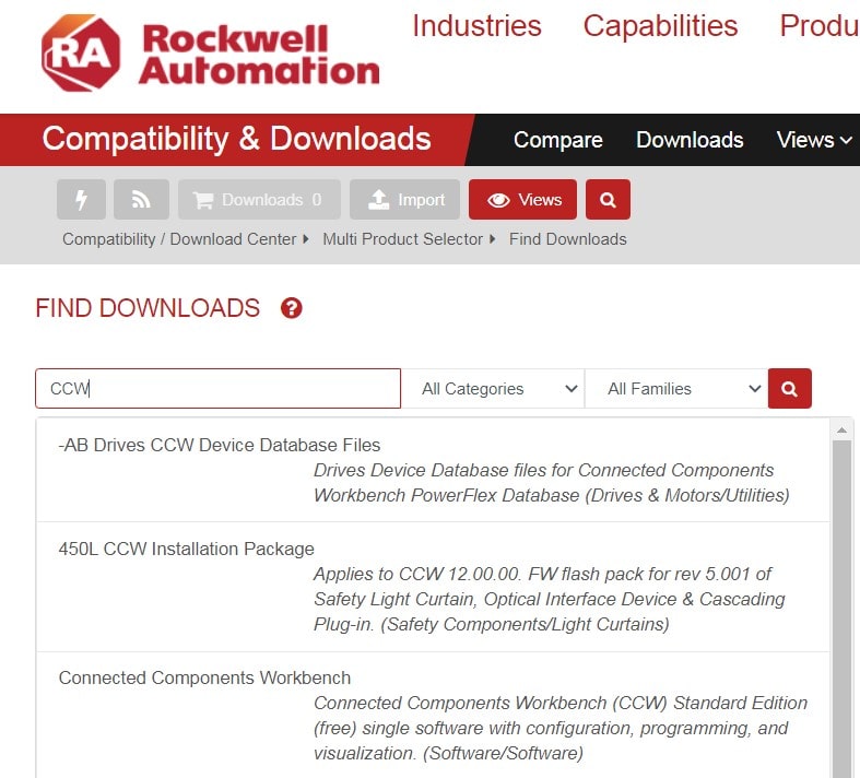
Your PowerFlex 70 drive probably has a wire scheme of one of the above examples, so it is important to note the two-wire or three-wire scheme before attempting to upgrade from PowerFlex 70 to PowerFlex 525 drive. Check your parameters shown on right to verify the mode you are operating in, so when you go to the PowerFlex 525 drive, you will know which wiring scheme to use to simulate the PowerFlex 70 drive you are replacing. Parameters that are associated with the PowerFlex 70 drive can be documented either by hand or using Connected Components WorkBench software – freeware on Rockwell Automation’s website. This can be found at the Product Compatibility and Download Center on their website. You may need a 1203-USB cable if you have no Ethernet access.

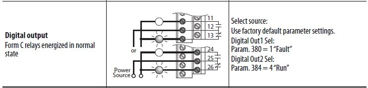
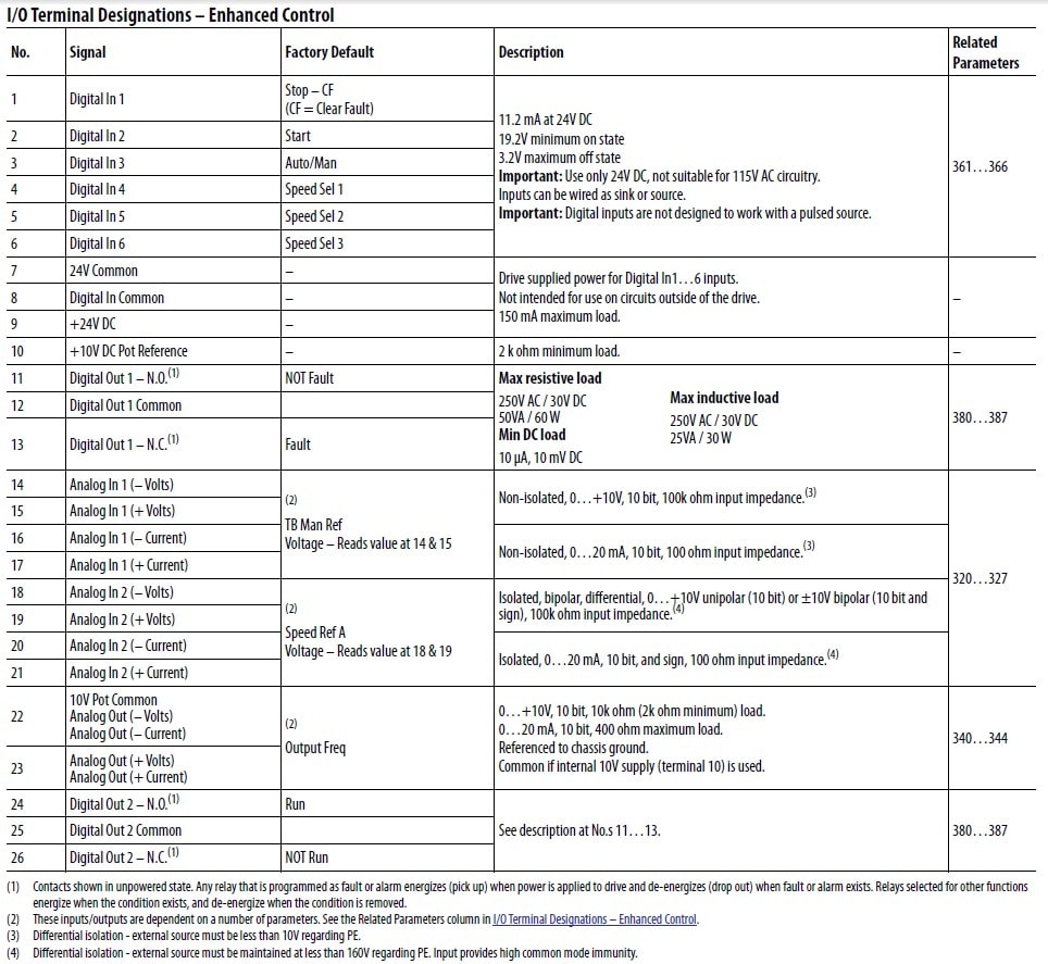
Above is an example of the two electromechanical relays and their terminal numbers. Please check these locations on the PowerFlex 70 drive I/O terminal strip.
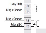
The PowerFlex 525 drive has two relays, connect PowerFlex 70 drive wiring to these two relays, make sure you know which wire is common and if the relay is Normally Open or Normally Closed.
Still to this day, analog signals are predominant in the AC drives market even with Ethernet increasing over the last few years. There are two types that IEEE standardized on many decades ago, 0-10VDC and 4-20mA signals. The 0-10V signals have a maximum distance of 30 ft. while 4-20mA signals are more noise immune and can go a distance of 2000 ft.
Most of the applications for analog input are used for speed reference to tell the drive what commanded speed to run at.
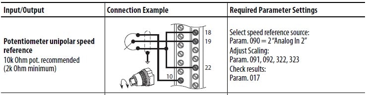
Above is a potentiometer of 10 Kohms (default) running a speed reference
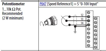
Above is a potentiometer of 10 Kohms (default) running a speed reference
POWERFLEX 70 DRIVE 4-20MA OPERATION
Speed Reference A by factory default is Analog Input 2
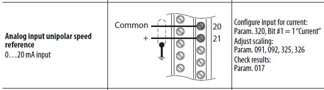
Analog Input 2(4-20mA) shown above
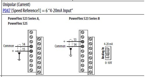
The 4-20 mA signals usually come from a PLC or a DCS. They can be generated through from any analog device (stand-alone). The illustration above shows the terminal connections. Please note, the analog in jumper must be moved to the position shown above the factory default is 0-10VDC.
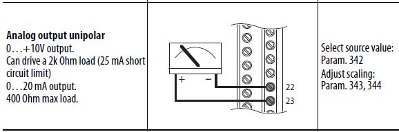
Above is an example of the only analog output on the PowerFlex 70 drive. When preparing to upgrade from PowerFlex 70 to PowerFlex 525 drive, carefully observe the notes to the right with parameters of interest. These parameters set the style of signal, the scaling, and signal loss if using 4-20mA. These all must be correct to get proper readings on the input end of the device it is wired to. Just a note: the 4-20mA signal can be read by a process meter with a clamp-on or the loop must be interrupted with a standard multimeter to check the output of the drive signal. This is different than measuring the 0-10VDC signal where the multimeter probes can go across the (+) and (–) terminals.
This concludes the I/O section of the blog, once the transfer of wiring takes place, you can begin programming your PowerFlex 525 drive. Please keep in mind, if the wires have been landed correctly, you will proceed one step at a time.
First, establish a “start” (three-wire) or “run” (two-wire) signal to the PowerFlex 525 drive then work on analog signals and relay outputs later, concentrate on one thing at a time. Remember, if you don’t feel comfortable yet, unhook the motor leads from the output of the drive (T1, T2, T3). The run indicator will come on when the drive starts, and the speed may or may not show a Hz value on the human interface module (HIM). Unhooking the drive from the motor will not damage the drive.
L1, L2, L3 are the AC input terminals to the drive, check the power terminals for 3 phase twice before turning the drive on, it could prevent damage to you and the drive. If you see ground faults and they rotate between phases U, V, W every time you start the drive, you have the input wires on the output of the drive. Continuing to start the drive without fixing it will cause drive failure. Sometimes the drive fails on the first start when wired backward. Be careful of wiring to the DC bus terminals with AC this is instant drive failure.
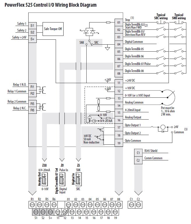
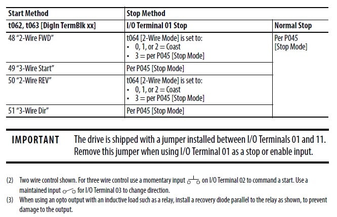
Please note, jumper between terminal 1 and terminal 11 must remain in when operating in two-wire mode. Three-wire mode must have a normally closed stop switch between terminal 1 and terminal 11.
Earlier in this blog, we mentioned prior to programming the PowerFlex 525 drive it is strongly recommended to get the parameters out of the PowerFlex 70 drive. This information is critical for upgrading from your PowerFlex 70 to PowerFlex 525 drive. Either having a changed parameter list from the PowerFlex 70 drive that might be a handwritten copy taped to the drive enclosure or extracting the parameters for the drive with Connected Component WorkBench. This software is a free download on Rockwell Automation’s PCDC.
Now let’s begin with the basic parameters that will get the drive to operate. First, let’s enter the motor data:
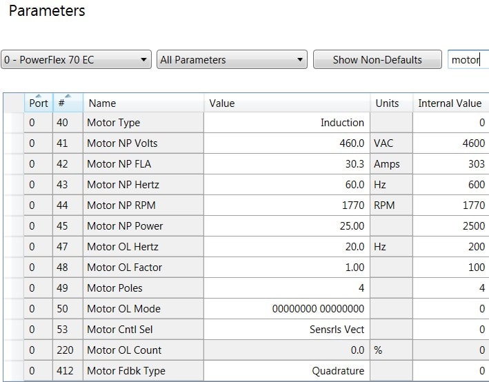
If this is a centrifugal pump or fan, parameter 53 should be set to Fan/Pump V/Hz value of “3.” The only motor parameter you need to set is parameter 42 and just enter the nameplate value on the motor. This is the simplest mode the drive can operate in.
Other loads that are more demanding on start that require more torque are called heavy duty loads (former term constant torque). These types of loads require the following data on the motor nameplate: Parameter# 40-53 leave Parameter 47 and 50 at factory default.
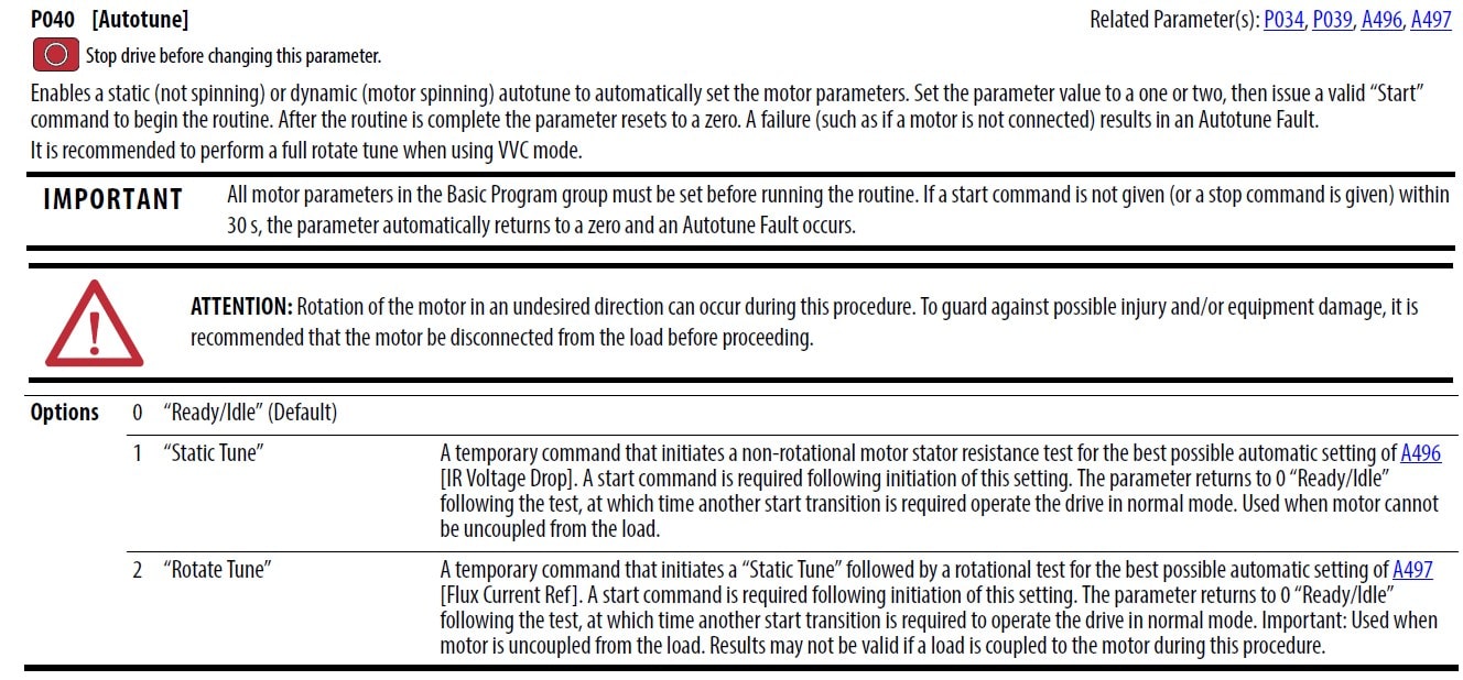
Heavy-duty loads require tuning. When you use sensorless vector mode, you will need to uncouple the load to do a rotate tune, which will accelerate and decelerate a few times to evaluate the resistance in the windings and winding leakage to the iron chassis of the motor. The autotune requires a start command set parameter 46 start source 1 to a value of “1,” this is the factory default. Please keep in mind the start source can only come from one location at a time; this is totally different than the architecture drives (PowerFlex 7series).
If you cannot uncouple the load from the motor, use the static tune and the motor will not rotate.
When you are ready to perform the autotune, go to parameter 40 and enter a value of “1” when you are clear and safe with either style of autotune, press the green start pushbutton on the HIM of the drive. When the autotune is complete the value in parameter 40 will return to a value of “0.” If the drive faults on the autotune, check the motor data to make sure it is correct. The drive has a range that it seeks from the motor data you entered in drive prior to the test.
If you do not tune the drive on heavy-duty loads, the drive may stall when you try to start it. The Hz value will not increase on start-up and the amps value will be high, thus the shaft will not move. Pumps and fans with normal duty characteristics do not require a lot of breakaway torque.
Recouple the motor to the load, now the drive is tuned. Please note, if you tuned the motor, if you change out the motor, you will need to repeat the autotune. V/Hz mode does not require tuning and motor changes are easier.
Please keep in mind, heavy-duty loads can run in V/Hz using the custom V/Hz. Changing the brake freq and break voltage will set the torque slope on startup. Please keep in mind, this is a trial-and-error process, the dynamics of a sensorless vector with boosting responses are far superior for breaking loads free.
After the autotune, the start command is coming from the green pushbutton for now. Press the start button, and the HIM should have a RUN indicator when modulating the drive output. Now change your start parameter 46 to where you need it to be (i.e., “terminal block” or “network”) and test it again to make sure you are receiving a start signal from your final location.
The speed reference can come from a variety of locations, just like the start command though you can only have a location at a time. For this blog on upgrading from PowerFlex 70 to PowerFlex 525 drive, we are using speed reference 1, and we will point it to an analog input which is wire to a 4-20mA signal (don’t forget to move the analog in jumper for 4-20mA).
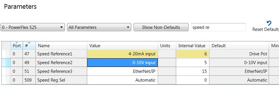
This is CCW software view. If you are using the keypad (cumbersome), the value of parameter 47 is “6.” Please keep in mind, the factory default of speed reference 1 is keypad or a value of “1.”
Analog outputs are tied to a certain parameter to give a value of 0-10VDC or 4-20mA to a PLC or DCS. The default for the PowerFlex 525 drive is output freq. This parameter is number 88. It can be scaled inside the drive like the analog inputs if you need to adjust it.
There are two relay outputs on the drive, they are preassigned but can be changed. The defaults are relay 1 is faulted and relay 2 is motor running.
The choices for the relay function are preprogrammed in the drive; these would be the values you have to choose from.
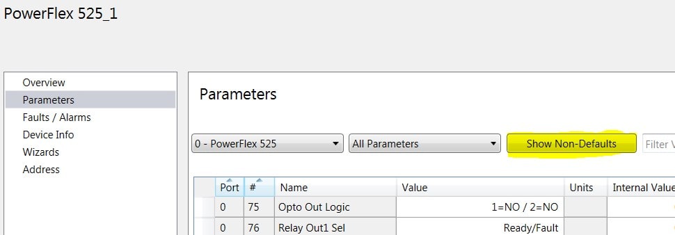
If you do use the CCW software, after uploading the PowerFlex 70 drive parameters from the drive, click the non-default pushbutton and the parameter list will change to only the modified parameter from factory default. Please keep in mind, this list will also show any parameters that are read-only, such as displays. This gives you a concise list of the parameters you need to program in the PowerFlex 525 drive.
In conclusion, if you’re using your legacy drive as a speed regular, upgrading the PowerFlex 70 to PowerFlex 525 drive is an excellent choice. If you are currently using flux vector in torque applications with PowerFlex 70 drive, then we strongly suggest replacing the drive with a PowerFlex 753 or PowerFlex 755 drive for the performance and capability. Back up your parameters ahead of time with CCW software so you have the proper parameter set to add into the PowerFlex 525 drive. Currently, there is no way to take that PowerFlex 70 drive file and download it into the PowerFlex 525 drive using the software.
Be as prepared as you can if you decide to run the PowerFlex 70 drive till it fails. Having the parameter set will save you minutes and possibly hours of repair time when you need to get up and running with a new drive.
Please feel free to contact us at any time with any questions or concerns.
Images used in this blog are © Rockwell Automation.