
Blog > Automation > Drive Modernization Part VI: PowerFlex 40 to PowerFlex 525
Drive Modernization Part VI: PowerFlex 40 to PowerFlex 525
7/13/21 | Scott Savage, Rexel Technical Consultant
Blog > Automation > Drive Modernization Part VI: PowerFlex 40 to PowerFlex 525
7/13/21 | Scott Savage, Rexel Technical Consultant
Welcome to the sixth part of the drive modernization series touching on Allen-Bradley® PowerFlex® drives. This series has provided many modernization solutions for legacy and mature drive to help assist you with the conversion. This installment covers migrating from PowerFlex 40 to PowerFlex 525 drives. Other titles in this series include:
The PowerFlex 40 series is superseded by the PowerFlex 525 series, these drives are considered a V/Hz drive with a mode called “sensorless vector.” Basically, sensorless vector control (SVC) has an autobooting algorithm to dynamically push more amps to the motor. When the drive load slows down, the motor and will maintain a commanded speed. These component style drives are speed regulators. Even though there is a flux vector mode, they are not capable of torque regulation like the PowerFlex 753 drives or PowerFlex 755 drives. Please consider the 750 series drives for torque following applications. Here is a helpful post that addresses programming torque regulation, please feel free to take a quick read if you have an application for this special mode of operation.
For migrating PowerFlex 40 to PowerFlex 525 drives, let’s start with some basics on what we need to accomplish to do a quick and easy installation. The most important task you can do is to back up the program using a program called Connected Components Workbench™ (CCW). It is a free download on the Rockwell Automation® website. A couple of methods can be used to access the drive with the software. You can go to each individual drive via “sneakernet” (plug into each drive individually with a cable) or via the network you may have in your location.
The download for CCW can be found on the Compatibility & Downloads offering on the Rockwell Automation website. It is strongly advised to download this software and retrieve your drive parameter sets long before the existing drive fails. Before you can migrate from PowerFlex 40 to PowerFlex 525 drives, you need to know the parameters in the old PowerFlex 40 drive to correlate to the new parameter set in the PowerFlex 525 drive. You cannot retrieve them once the old drive has failed, and this makes the transition extremely arduous. The time saved will lead you on your way to a fast and professional approach when the time is at hand!
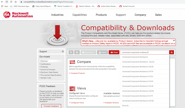
The Rockwell Automation website has the Compatibility & Downloads feature, search for CCW acronym or “Connected Components Workbench.”
This software will be used in coordination with RSLinx® Classic communication software to talk to the drive. The communication software has all the drivers in the library to talk to the drive. RSLinx software comes with the CCW download package, so if you don’t have it, you will have RSLinx software when CCW is installed.
If you choose not to use the software, it is a great tool for using offline and using the filter in the software to find parameters by name or by number instead of using the user manual and the time-consuming hunt and peck approach. If you don’t have a laptop, please load it on an engineering desktop and write down the parameters of interest as an offline tool. The software loads the parameters and default values so you can make some decisions on install. These drives do not have a copycat function in the keypad because the keypad is an integral drive. Once again, please back up your programs prior to a failure.
If you have a remote human interface module (HIM), you can back up your programs with these two devices:
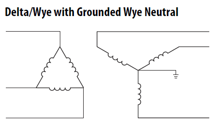
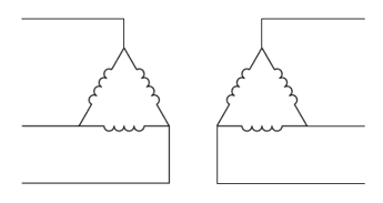
Both PE-A(MOV) and PE-B (common mode output filter) are installed.
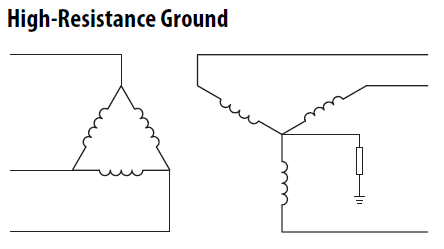
Both PE-A(MOV) and PE-B (common mode output filter) are removed.
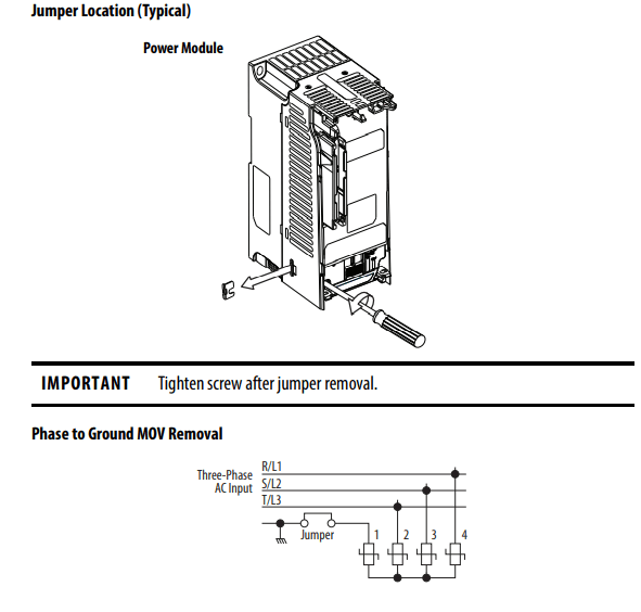
Please keep in mind, a resistive grounding scheme also allows the first ground fault to occur. Though not mandatory, please keep in mind, a line reactor in front of these drives is strongly recommended. If the KVA is 10X KVA value of the HP of the drive, then a line reactor becomes mandatory (i.e., a 100KVA transformer supplying a 10 HP requires a line reactor). The PowerFlex 525 drive does not have an internal DC link inductor till frame size E. There is no DC link inductor on the DC bus till frame E.
The motor needs a solid bond from the drive to the motor. The ground wire or multiple ground wires needs to go directly from one of the two green ground screws on the drive chassis to the conduit box on the motor. Do not place the ground from the motor to a common ground bus in the drive cabinet or the common ground bus in a motor control center (MCC), this injects noise that seeks noise generated from the drive output to other areas in your facility. This is a physical requirement for a successful drive installation. In addition, variable frequency drive (VFD) shielded cable should be on the output side of the drive to cancel noise, which could be contained to the output wires or airborne in the output cable.
Please avoid THHN, if possible. Thermoset insulation “cold sets” and is also susceptible to moisture. XHHN wire is preferred and shielding using VFD cable is extremely important to the successful commissioning of the drive. Inspect all wires down at the motor end of the drive for corona damage (pitting) and replace, if needed.
To ensure a good bond at the motor, remove all paint on the motor junction box, all currents need to cancel to zero, including noise, and drives should be considered “noise generators.” The ground wire from the motor goes directly back to the green drive ground screws on the chassis of the drive. Good practices lead to fewer problems later when the drive is operating. Please do not assume that because the drive operated properly before it will continue to operate in the same manner. Once again, the grounding path is a physical practice and must be followed specifically upon installation.
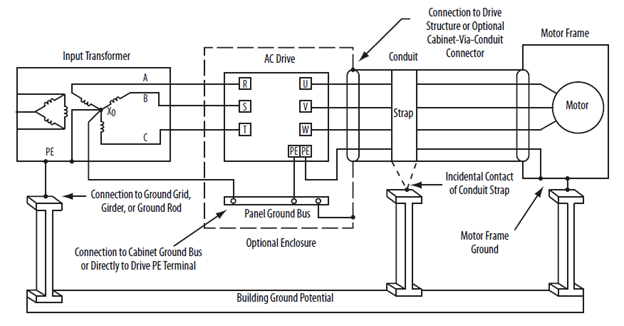
Please note, the PE connections from the motor frame to the drive PE screw are grounded at both ends. This holds true for all distribution systems unlike the jumpers discussed above.
If you are using a VFD cable with proper shielding and braiding to help capture the noise on the output of the drive, make sure all shields and braids are terminated on both ends of the cable—the drive chassis and motor chassis. All bare bonding wires, which could be multiples depending on the style of cable, must all be bonded uninterrupted to the drive, not to a common ground bus. The other end of the shielded cable must also be terminated to the frame of the motor. Please use low impedance terminals or lugs and remove any paint on the motor conduit box for a low impedance connection. Since this drive has no output filter, provide the best path to the drive from the motor.
If you have an MCC, the drive grounds (bonds) do not terminate on the MCC ground bus. They need to go directly to the drive the noise was generated from. Keep in mind, noise can be airborne and the foil shields (usually two shields for 100% coverage need to get back to the drive to cancel out all currents from the drive itself). If you do not have VFD shielded cable, the single ground will act as the best return path to the drive.
Noise degrades all kinds of electronic equipment. Sometimes the damage is months down the road. Improper grounding will result in premature failure of all low impedance paths where the noise will travel to go back to where it was generated from (the drive), even internal drive components. Your most important wire is your ground and how physically it is connected. A drive can be wired to code and still be bonded improperly.
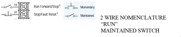
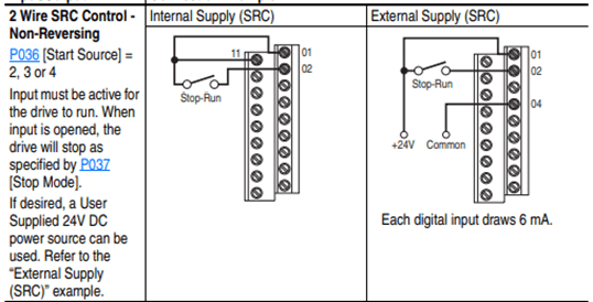
Quickly, let’s review two-wire control concepts, Allen-Bradley traditionally uses the term “Run” for a two-wire control term. Run Forward and Run Reverse are used for two-wire control.
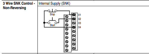
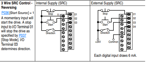
Three-wire control uses a momentary switch versus the two-wire control. Some applications and environments require three-wire control. Either method works—it becomes a matter of preference to which control method you choose to standardize on.
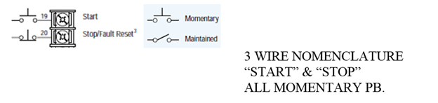
Please note, terminals 19 and 20 are not the correct terminal numbers for the PowerFlex 525 drive. This is for concept only, showing the electrical symbols for momentary and maintained switches. Three-wire and two-wire electrical symbols and their nomenclature of “Start Stop” and “Run” are important to observe. These terms and symbols can’t be mixed, rather you have momentary or maintained devices.
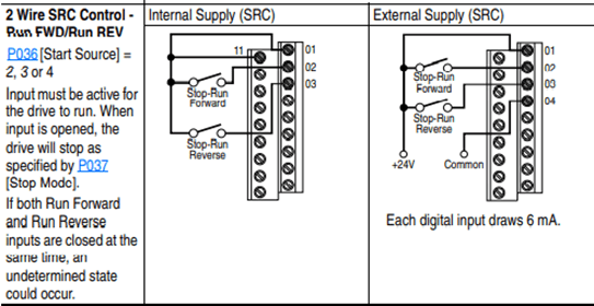
If you have three-wire control, terminal two will have a momentary pushbutton instead of a maintained switch. If you have two-wire control, the jumper should remain between terminals 1-11 on PowerFlex 525 drives. This jumper determines two-wire control or three-wire control, leaving the jumper is the proper installation for two-wire control. If you are hardwired to a PLC, and wired to a relay output, two-wire control is very common.
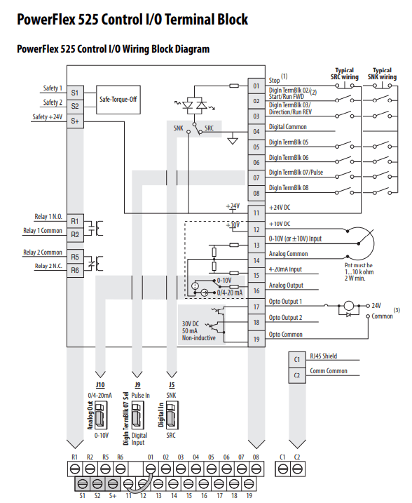
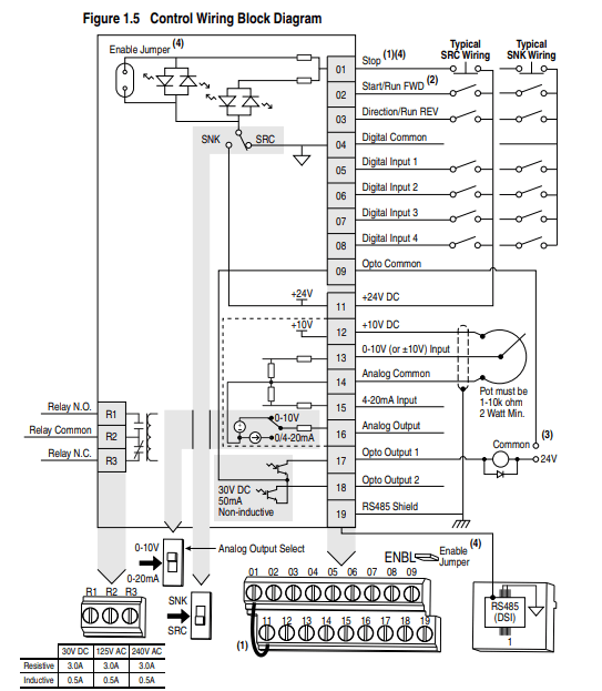
Note on the PowerFlex 40 drive, you have an SRC/SNK switch, observe its position, most common is SRC to supply I/O positive voltage to the terminals shown above in the PowerFlex 40 drive example. The sourcing or sinking in the PowerFlex 525 drive is determined by wiring to the example shown in the PowerFlex 525 drive I/O wiring and wiring to either negative switching (SNK) or positive switching (SRC) and setting J5 to the proper mode shown above. The default is set to SRC mode, it is a safer mode in case the supply wire goes to ground.
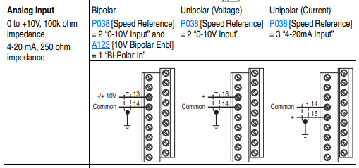

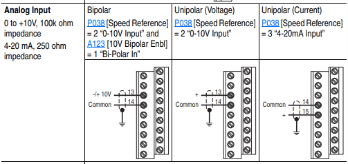
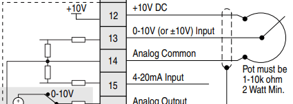
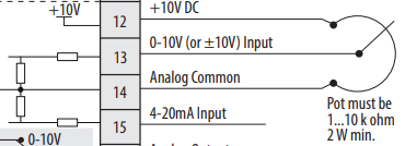
Potentiometer terminals are identical from PowerFlex 40 to PowerFlex 525 drives. A 10K potentiometer gives you a full range from 0-60Hz. Other resistance values on the potentiometer must be scaled to achieve full range of speed (i.e., in a 5K potentiometer you would have to adjust the maximum frequency on the drive to 120Hz to achieve 60 Hz. output on the drive).
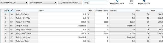
A 4-20mA signal is wired to terminal 16, and the common (-) jumper should be on the 4-20 setting shown below. Signal loss is programmed in the drive as an offset to achieve 4-20 mA from the default of 0-20 mA.

Observe parameter 65 in the PowerFlex 40 drive to determine what the analog output is programmed to transmit for information.

Above parameter 65 is programmed to follow output frequency of the drive.
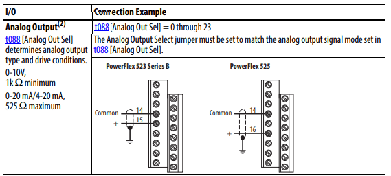
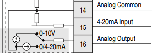
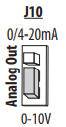
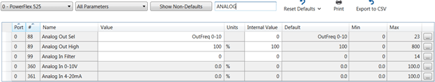
The PowerFlex 525 drive also has a jumper for the analog output. The factory default is 0-10V, 4-20mA can be achieved by strapping the jumper to the 0/4-20mA location shown below.
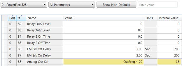
Change parameter 88 in the PowerFlex 525 drive to the same function as parameter 65 in the PowerFlex 40 drive.

If 4-20 mA is needed, then parameter 88 would be set for the 4-20mA selection in parameter 88 shown below as an internal numeric value of “16.”
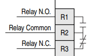
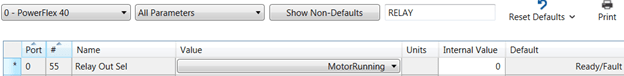
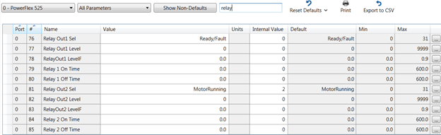
In this example, the relay for the PowerFlex 40 drive is set to motor running; this is commonly used in a lot of applications. This parameter needs to be examined to see what the relay function is in the PowerFlex 40 drive and programmed in the relay for the PowerFlex 525 drive.
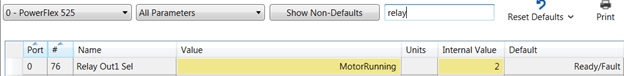
The value of parameter 55 in the PowerFlex 40 drive needs to be programmed in parameter 76 in the PowerFlex 525 drive.
Now we are ready to program the drive, please keep in mind using Connected Components Workbench (CCW) and uploading the parameters in all your older PowerFlex 40 drives saves a lot of time and energy. Please back your parameters off all your existing drives to make the project easy.
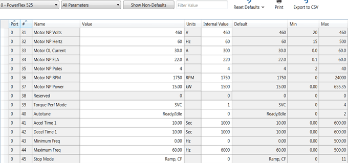
Use the parameters in the PowerFlex 40 drive to set your parameter values in the PowerFlex 525 drive, if possible, the nomenclature is the same, if you do not have the parameter set, then you must program and make the decisions to make sure the parameters set is correct, so the drive operates correctly.

There are a few differences with ethernet when migrating from PowerFlex 40 to PowerFlex 525 drives. The PowerFlex 40 drive has a 22-COMM-E adapter under the cover of the drive. It is connected via a ribbon cable and plugs into the drive. The PowerFlex 525 drive has an embedded Ethernet port color-coded blue. PowerFlex 525 drives now have direct access to parameters inside the drive for communication (e.g., IP address, subnet masking, and gateway configuration if used outside the facility).
NOTE: The IP address on your LAN adapter in the computer must be set for the same subnet as the drives you wish to communicate with.
The three basic ways to communicate between the PLC controller/laptop to the PowerFlex 525 drive:
You can assign the static IP address a couple of different ways:
This example would be the basics to assign your IP address to the drive. We will use Class C subnet on network 192.168.1.x x=host ID (device).
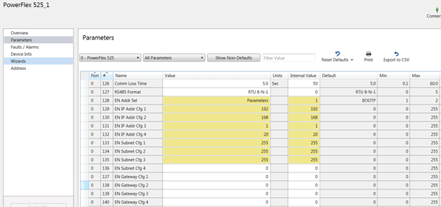
NOTE: Parameter 128 when parameters 129-136 are changed must be set to “parameters” not “BOOTP.” Cycle power to make sure BOOTP is disabled. If programmed correctly, the adapter will hold the IP addresses and proper subnet masking values.
To connect to the drive, make sure your static IP address on your computer adapter is set for an IP address that is on the network ID (192.168.1), please keep in mind this is class C subnet addressing. The laptop should be a unique host ID. Let’s choose 192.168.1.20, and it now is assigned to the LAN adapter on the Windows® workstation. Assign the LAN adapter on the computer through Windows Control Panel, System, Device Manager, or equivalent depending on the Windows operating system.
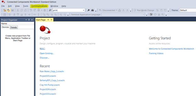
Once drive power is cycled, use a software package that was installed with CCW software called RSLinx from Rockwell Automation. There is an icon called RSWho symbol; it looks like this:
It allows you to browse the network and query all the nodes on your subnet. There are two types of ethernet drivers in the RSLinx library that are available for your use. Please use the ETHIP driver and not the ETH generic driver, which needs the nodes scheduled in the driver scanning list. Ethernet/IP will auto browse and discover all devices on the network using the Ethernet/IP protocol.
You will need to load the ethernet driver in RSLinx. To do this, go to the pulldown menu at the top of the software window “Communications.”
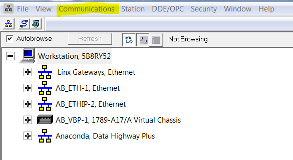
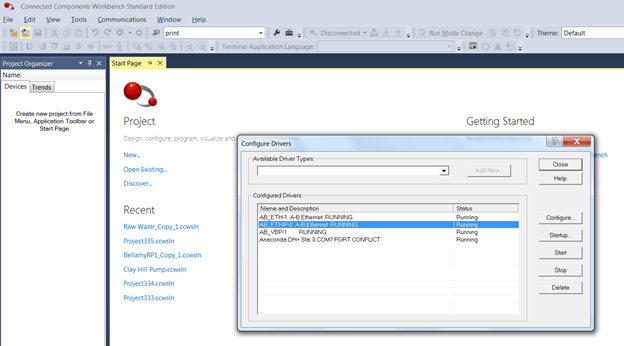
Choose “Configure Drivers.” Now, use the pulldown menu for “Available Driver Types” to select a driver.
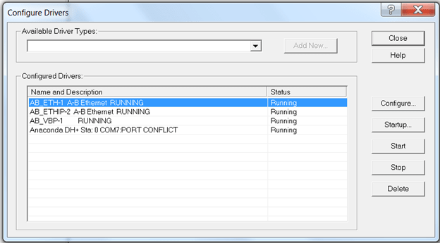
Choose an ETHIP driver. You can give the ETHIP driver a specific tag name or leave the driver’s name at the default. In this case, we have left it at the default for identification purposes.
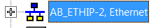
Now, you should be able to invoke an RSWho and query all devices on the network. Leave the Configure Drivers screen and click on the ETHIP driver on “+” and see what populates like what is shown below:
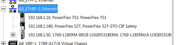
The screen should expand showing devices on the network shown above, this is strictly an example of the communications software.
Now that communication to the drive has been established with RSLinx, you can proceed to go online with the laptop using Connected Components Workbench and view many parameters in the drive. You can also trend parameters such as amps, frequency, DC bus Volts, etc.
The communications look identical to your RSLinx experience in CCW. Click on the communications pulldown text (highlighted), and you will see the identical screens that were available in RSLinx. Each device in the network will tie to their IP addresses once you choose the driver in RSLinx. The example we have chosen is ETHIP shown below:
Please keep in mind, you can use other drivers such as the serial driver for the 1203-USB through RSLinx. Since the RS232 driver is at 115,200 Kbits/sec, it is not recommended for trending data from the drive.
Have fun experiencing CCW. If you have not used it before, it is a powerful software tool when programming the drive. The filter in the parameters window helps search for parameters by name or by number, allowing fast access to the parameters you need to change to get your drive running fast.
Please remember to back up your parameter files in CCW, so when the day comes you need to quickly download the program into a new drive, you will be ready!
Thank you for reading this blog about migrating from PowerFlex 40 to PowerFlex 525 drives. I hope it gave some insight into the two drives so you can modernize your plant when necessary! Please contact us with any questions you may have.
The Literature Library on the Rockwell Automation website has technical documents for the PowerFlex 525 drive and the PowerFlex 520 series family.