
Blog > Automation > Drive Modernization Part VII: PowerFlex 4 to PowerFlex 523
Drive Modernization Part VII: PowerFlex 4 to PowerFlex 523
8/3/21 | Scott Savage, Rexel Technical Consultant
Blog > Automation > Drive Modernization Part VII: PowerFlex 4 to PowerFlex 523
8/3/21 | Scott Savage, Rexel Technical Consultant
Welcome to the seventh part of the drive modernization series touching on Allen-Bradley® PowerFlex® drives. This series has provided many modernization solutions for legacy and mature drive to help assist you with the conversion. This installment covers migrating from PowerFlex 4 to PowerFlex 523. Other titles in this series include:
The Powerflex 4 series is superseded by the Powerflex 523 series, these drives are considered V/hz drives with a mode called “sensorless vector.” Basically, sensorless vector control (SVC) has an autoboosting algorithm to dynamically push more amps to the motor, when the drive load slows down, the motor and will maintain a commanded speed. These component style drives are speed regulators.
For migrating PowerFlex 4 to PowerFlex 523, let’s start with some basics on what we need to accomplish to do a quick and easy installation. The most important task you can do is to back up the program using a program called Connected Components Workbench™ (CCW). It is a free download on the Rockwell Automation® website. A couple of methods can be used to access the drive with the software. You can go to each individual drive via “sneakernet” (plug into each drive individually with a cable) or via the network you may have in your location.
The PowerFlex 523 only has a DSI port. The drives can be daisy-chained together with wire and a resistor on each end of the physical network (terminators). You can access the network via a 1203-USB cable through one of the drive DSI ports ( coded red). This drive does not have an ethernet port unless you have an add-on card called a 25-COMM-E2P dual-port card added in the accessory port on the drive.
The download for CCW can be found on the Compatibility & Downloads offering on the Rockwell Automation website. It is strongly advised to download this software and retrieve your drive parameter sets long before the existing drive fails. Before you can migrate from PowerFlex 4 to PowerFlex 523, you need to know the parameters in the old PowerFlex 4 drive to correlate to the new parameter set in the PowerFlex 523 drive. You cannot retrieve them once the old drive has failed, making the transition extremely arduous. The time saved will lead you on your way to a fast and professional approach when the time is at hand!
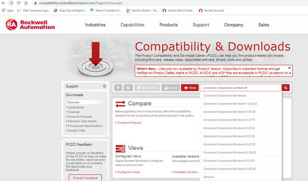
The Rockwell Automation website has the Compatibility & Downloads feature, search for CCW acronym or “Connected Components Workbench.”
This software will be used in coordination with RSLinx® Classic communication software to talk to the drive. The communication software has all the drivers in the library to talk to the drive. RSLinx software comes with the CCW download package, so if you don’t have it, you will have RSLinx software when CCW is installed.
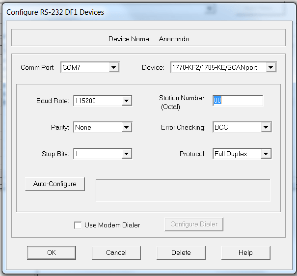
The 1203-USB cable can be used to connect to the PowerFlex 523 drive. Under the communications pull-down menu, you will choose RS-232 driver for configuration. The boxes must be filled in properly after the driver configuration window appears. Please fill in the details to get the driver to operate properly.
Here is the configuration, the example is for com port 7 on the laptop, yours may be different, so please check under windows Device Manager in serial com ports to see which port is assigned to the 1203-USB device, the icon will be a six-sided A-B “meatball,” as we call it, if the cable is recognized by the Windows operating system. The configuration box is shown below:
If you choose to use the software, it is a great tool for using offline and using the filter in the software to find parameters by name or by number instead of using the user manual and the time-consuming hunt and peck approach. If you don’t have a laptop, please load it on an engineering desktop and write down or print the parameters of interest as an offline tool. The software loads the parameters and default values, so you can make some decisions on install. These drives do not have a copycat function in the integral keypad. Once again, please backup your programs prior to a failure.
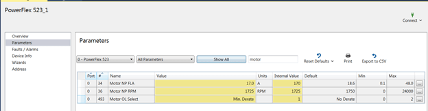
The filter in CCW is shown above, the changed parameters are coded yellow in the show all screen. Parameter 34, 36, and 493 were changed in the drive with the software.
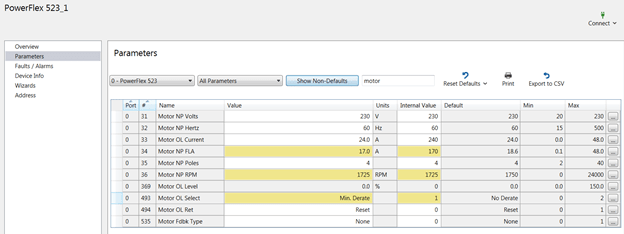
Shown above is the show non-defaults screen, observe the print icon to print the files to Adobe Acrobat format. Hit Show All to go back to the screen which shows all parameters.
If you have a remote human interface module (HIM), you can backup your programs using HIM copycat with these two devices:
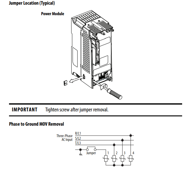
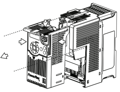
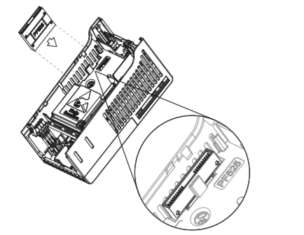
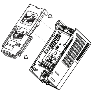
Both PE-A(MOV) and PE-B (common mode output filter) are removed.
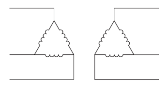
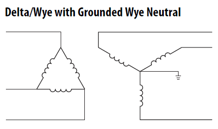
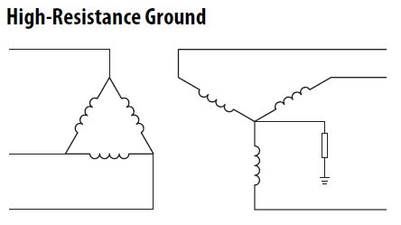
Know your distribution system prior to installation of the drive. If the transformer is not solidly grounded (resistive or delta secondary), you must remove the jumper for the MOVs. Failure to remove the jumper will cause damage to the MOVs and the drive will fail. These drives are not repairable after damage. It is also mandatory to place a line reactor in front of the drive on all delta systems. Failure to install a line reactor may cause high current flow upon a distribution fault, and if the system has one ground fault, it could result in severe damage between the two ground paths in your facility. The PowerFlex 523 drive does not have PE-B (common mode filter in PowerFlex750 drive), only the MOV jumper. Below illustrates the location of this jumper.
Please keep in mind, a resistive grounding scheme also allows the first ground fault to occur. Though not mandatory, please keep in mind, a line reactor in front of these drives is strongly recommended. If the KVA is 10X KVA value of the HP of the drive, then a line reactor becomes mandatory (i.e., a 100KVA transformer supplying a 10 HP requires a line reactor). The PowerFlex 525 drive does not have an internal DC link inductor till frame size E. There is no DC link inductor on the DC bus till frame E. It is strongly recommended to place a line reactor in front of the drive regardless of the transformer size upstream of the drive.
The motor needs a solid bond from the drive to the motor. The ground wire or multiple ground wires needs to go directly from one of the two green ground screws on the drive chassis to the conduit box on the motor. Do not place the ground from the motor to a common ground bus in the drive cabinet or the common ground bus in a motor control center (MCC), this injects noise that seeks noise generated from the drive output to other areas in your facility. This is a physical requirement for a successful drive installation. In addition, variable frequency drive (VFD) shielded cable should be on the output side of the drive to cancel noise, which could be contained to the output wires or airborne in the output cable.
Please avoid THHN, if possible. Thermoset insulation “cold sets” and is also susceptible to moisture. XHHN wire is preferred and shielding using VFD cable is extremely important to a successful commissioning of the drive. Inspect all wires down at the motor end of the drive for corona damage (pitting) and replace, if needed.
To ensure a good bond at the motor, remove all paint on the motor junction box, all currents need to cancel to zero, including noise, and drives should be considered “noise generators.” The ground wire from the motor goes directly back to the green drive ground screws on the chassis of the drive. Good practices lead to fewer problems later when the drive is operating. Please do not assume that because the drive operated properly before it will continue to operate in the same manner. Once again, the grounding path is a physical practice and must be followed specifically upon installation.
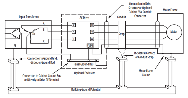
Please note, the PE connections from the motor frame to drive PE screw are grounded at both ends. This holds true for all distribution systems unlike the jumpers discussed above.
If you are using a VFD cable with proper shielding and braiding to help capture the noise on the output of the drive, make sure all shields and braids are terminated on both ends of the cable—the drive chassis and motor chassis. All bare bonding wires, which could be multiples depending on the style of cable, must all be bonded uninterrupted to the drive, not to a common ground bus. The other end of the shielded cable must also be terminated to the frame of the motor. Please use low impedance terminals or lugs and remove any paint on the motor conduit box for a low impedance connection. Since this drive has no output filter, provide the best path to the drive from the motor.
If you have an MCC, the drive grounds (bonds) do not terminate on the MCC ground bus. They need to go directly to the drive the noise was generated from. Keep in mind, noise can be airborne and the foil shields (usually two shields for 100% coverage need to get back to the drive to cancel out all currents from the drive itself). If you do not have VFD shielded cable, the single ground will act as the best return path to the drive.
Noise degrades all kinds of electronic equipment. Sometimes the damage is months down the road. Improper grounding will result in premature failure of all low impedance paths where the noise will travel to go back to where it was generated from (the drive), even internal drive components. Your most important wire is your ground and how physically it is connected. A drive can be wired to code and still be bonded improperly.
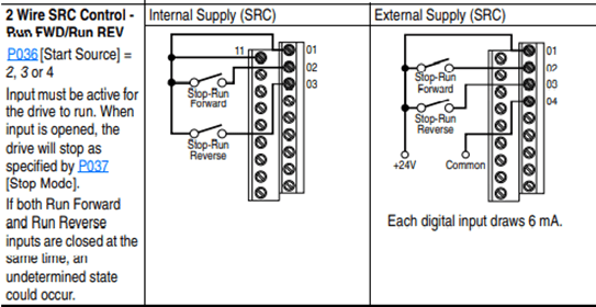
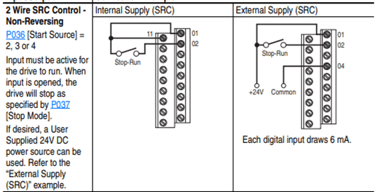
Quickly, let’s review two-wire control concepts, Allen-Bradley traditionally uses the term “Run” for a two-wire control term. Run Forward and Run Reverse are used for two-wire control.
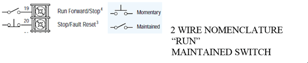
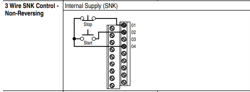
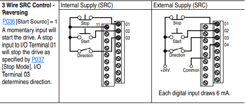
Three-wire control uses a momentary switch versus the two-wire control. Some applications and environments require three-wire control. Either method works—it becomes a matter of preference to which control method you choose to standardize on.
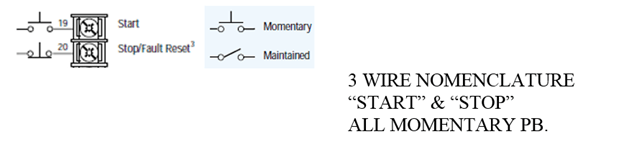
Please note, terminals 19 and 20 are not the correct terminal numbers for the PowerFlex 523 drive. This is for concept only, showing the electrical symbols for momentary and maintained switches. Three-wire and two-wire electrical symbols and their nomenclature of “Start Stop” and “Run” are important to observe. These terms and symbols can’t be mixed together, rather you have momentary or maintained devices.
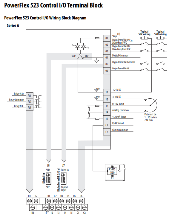
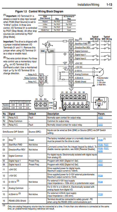
If you have three-wire control, terminal two will have a momentary pushbutton instead of a maintained switch. If you have two-wire control, the jumper should remain between terminals 1-11 on PowerFlex 523 drives. This jumper determines two-wire control or three-wire control, leaving the jumper is the proper installation for two-wire control. If you are hardwired to a PLC, and wired to a relay output, two-wire control is very common.
Note on the PowerFlex 4 drive, you have an SRC/SNK switch, observe its position, most common is SRC to supply I/O positive voltage to the terminals shown above in the PowerFlex 4 drive example. The sourcing or sinking in the PowerFlex 523 drive is determined by wiring to the example shown in the PowerFlex 523 drive I/O wiring and wiring to either negative switching (SNK) or positive switching (SRC) and setting J5 to the proper mode shown above. The default is set to SRC mode, it is a safer mode in case the supply wire goes to ground.
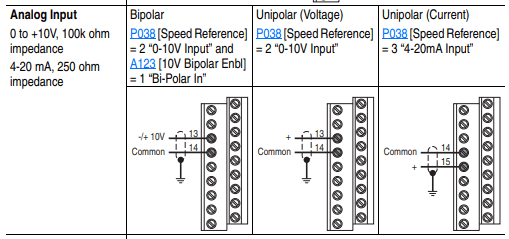
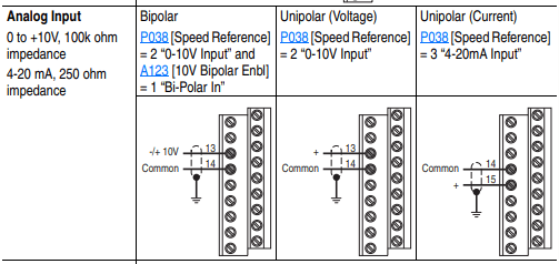
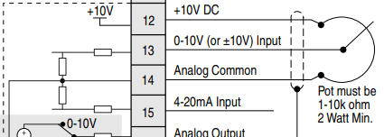
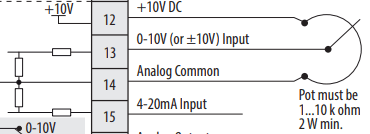
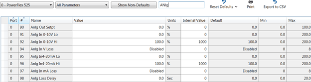
Potentiometer terminals are identical from PowerFlex 4 to PowerFlex 523. A 10K potentiometer gives you a full range from 0-60hz. Other resistance values on the potentiometer must be scaled to achieve full range of speed (i.e., a 5K potentiometer you would have to adjust the maximum frequency on the drive to 12 0hz to achieve 60 Hz. output on the drive).
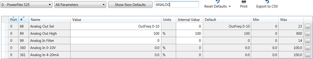
There are no analog outputs on this, please consider the PowerFlex 525 drive.
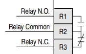
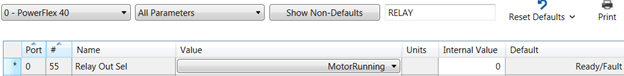
In this example, the relay for the PowerFlex 4 drive is set to motor running; this is commonly used in a lot of applications. This parameter needs to be examined to see what the relay function is in the PowerFlex 4 drive and programmed in the relay for the PowerFlex 523 drive.
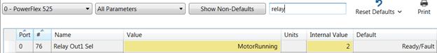
The value of parameter 55 in the PowerFlex 4 drive needs to be programmed in parameter 76 in the PowerFlex 523 drive.
Now we are ready to program the drive, please keep in mind using CCW and uploading the parameters in all your older PowerFlex 4 drives saves a lot of time and energy. Please back your parameters off all your existing drives to make the project easy.
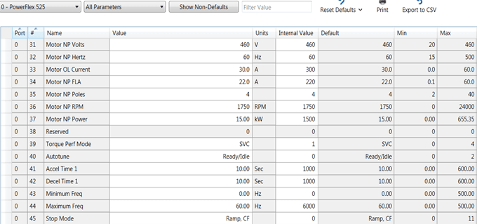
Use the parameters in the PowerFlex 4 drive to set your parameter values in the PowerFlex 523 drive if possible, nomenclature is the same. If you do not have the parameter set, then you must program and make the decisions to make sure the parameters set is correct so the drive operates correctly.

7. Set your speed reference (only from one source) parameter 47.
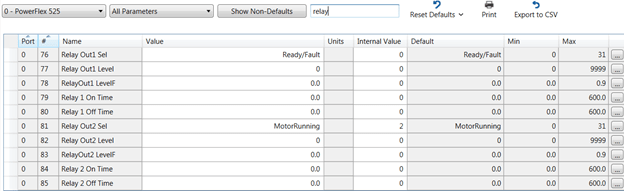
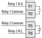
The PowerFlex 523 drive only has Relay 1, for two relays please consider the PowerFlex 525.
There are a few differences with ethernet when migrating from PowerFlex 4 to PowerFlex 523 drives. The PowerFlex 4 drive has a 22-COMM-E adapter under the cover of the drive. It is connected via a ribbon cable and plugs into the drive. The PowerFlex 523 drive has an add-on module (25-COMM-E2P) dual-port adapter. PowerFlex 523 drives now have direct access to parameters inside the drive for communication (e.g., IP address, subnet masking, and gateway configuration if used outside the facility with gateway).
NOTE: The IP address on your LAN adapter in the computer must be set for the same subnet as the drives you wish to communicate with.
The three basic ways to communicate between the PLC controller/laptop to the PowerFlex 523 drive:
You can assign the static IP address a couple of different ways:
This example would be the basics to assign you IP address to the drive. We will use Class C subnet on network 192.168.1.x x=host ID (device):
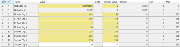
NOTE: Parameter 4 in the 20-COMM-E2P (PORT 2) when parameters 6-12 are changed must be set to “parameters” not “BOOTP.” Cycle power to make sure BOOTP is disabled. If programmed correctly, the adapter will hold the IP addresses and proper subnet masking values.
To connect to the drive, make sure your static IP address on your computer adapter is set for an IP address that is on the network ID (192.168.1), please keep in mind this is class C subnet addressing. The laptop should be a unique host ID. Let’s choose 192.168.1.20, and it now is assigned to the LAN adapter on the Windows® workstation. Assign the LAN adapter on the computer through Windows Control Panel, System, Device Manager, or equivalent depending on the Windows operating system.
Once drive power is cycled, use a software package that was installed with CCW software called RSLinx from Rockwell Automation. There is an icon called RSWho symbol looks like this:
It allows you to browse the network and query all the nodes on your subnet. There are two types of ethernet drivers in the RSLinx library that are available for your use. Please use the ETHIP driver and not the ETH generic driver, which needs the nodes scheduled in the driver scanning list. Ethernet/IP will auto browse and discover all devices on the network using the Ethernet/IP protocol.
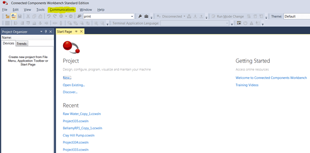
You will need to load the ethernet driver in RSLinx. To do this, go to the pulldown menu at the top of the software window “Communications.”
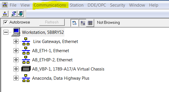
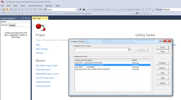
Choose “Configure Drivers.” Now, use the pulldown menu for “Available Driver Types” to select a driver.
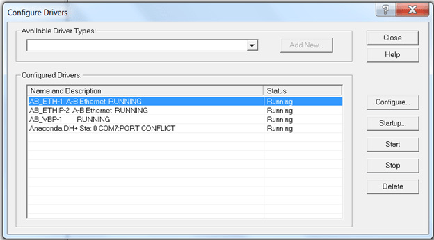
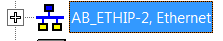
Choose an ETHIP driver. You can give the ETHIP driver a specific tag name or leave the driver name at the default. In this case, we have left it at the default for identification purposes.
Now, you should be able to invoke an RSWho and query all devices on the network. Leave the Configure Drivers screen and click on the ETHIP driver on “+” and see what populates similar to what is shown below:
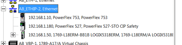
The screen should expand showing devices on the network shown above, this is strictly an example of the communications software.
Now that communication to the drive has been established with RSLinx software, you can proceed to going online with the laptop using CCW and view many parameters in the drive. You can also trend parameters such as amps, frequency, DC bus Volts, etc.
The communications look identical to your RSLinx software experience in CCW. Click on the communications pulldown text (highlighted), and you will see the identical screens that were available in RSLinx. Each device in the network will tie to their IP addresses once you choose the driver in RSLinx. The example we have chosen is ETHIP shown below:
Please keep in mind, you can use other drivers such as the serial driver for the 1203-USB through RSLinx. Since the RS-232 driver is at 115,200 Kbits/sec, it is not recommended for trending data from the drive.
Have fun experiencing CCW. If you have not used it before, it is a powerful software tool when programming the drive. The filter in the parameters window helps search for parameters by name or by number, allowing fast access to the parameters you need to change to get your drive running fast.
Please remember to back up your parameter files in CCW, so when the day comes you need to quickly download the program into a new drive, you will be ready!
Thank you for reading this blog about migrating from PowerFlex 4 to PowerFlex 523 drives; I hope it gave some insight into the two drives so you can modernize your plant when necessary! Please contact us with any questions you may have.
The Literature Library on the Rockwell Automation website has technical documents for the PowerFlex 523 drive and the PowerFlex 520 series family.
https://www.rockwellautomation.com/en-us.html
Documents of interest:
This is a view from Connected Components Workbench, if you are using the HMI navigate to the proper parameter. Notice the port number for the drive parameters are all in port 0 unlike the PowerFlex 750 drive, which has a backplane and multiple ports to insert all kinds of different modules.
As mentioned above, the PowerFlex 755 drive is not the primary focus of this blog. It is important to remember that all these practices can be used in the PowerFlex 755 drive with expansion modules. The PowerFlex 755 drive main control board only has one digital input and one relay output and is considered a system drive with primary strength using ethernet control via a ControlLogix processor with direct access to the drive parameters.
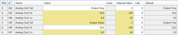
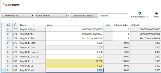
Let’s look at port 0 first, since it has an analog output available. If you are using one output, this is like the PowerFlex 700 drive. This example shows the changes involved to make the channel 4-20 mA. For the first channel, let’s look at scaling. The default is 0-10 V DC shown below. Please change to 20 mA high upper range (parameter 280) and 4 mA for low (parameter 281). This is shown in yellow on the screen capture. Parameter 270 should now show a “1” on the right-hand bit to verify the channel has changed to 4-20 mA. If it does not edit the bit on the right, make it a “1” using the HMI or Connected Components Workbench software.
Notice the nomenclature is slightly different. “Output frequency” in the PowerFlex 700 drive now has been renamed “mtr vel fdbk” this is the new equivalent in the PowerFlex 750 series drives. Notice the port 0 is the same as the PowerFlex 700 drive because we are in the main control board for both drives. This is the easiest transition to the new analog output channel.
The question to ask here is do you have more than one output? In this case, then you need an additional expansion module.
HINT: The analog channel value can be observed to check the magnitude of that channel (parameter 282), it is strongly advised the drive is to make sure it is operating properly and the scaling is correct.
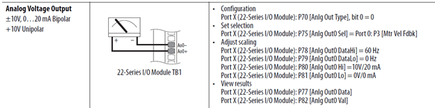
Now that you have programmed the 4-20 mA, connect your device, shown is a 22 series expansion module that has two ports Ao0, and Ao1. Assign the values shown below if you are using the expansion ports.
We have installed an expansion module in port 4. Now there are two analog out channels. The scaling is the same as above. You will assign a parameter from port 0 to the analog output sel parameters 75 or 85 in the host module in port 4 and tie them to the functions in port 0. Check the channel values in parameters 82 and 92 in the drive while the drive is running to verify limits and spans are correct. Parameter 70 if in “current” mode will show a “1” on the far right if it is set for 0-20 mA or 4-20 mA.
Relay outputs can be assigned to such events as “running” or “faulted,” not running and the drive is in peril. A variety of options can be used depending on the application the drive is operating in for an environment. Let’s examine the terminals on the PowerFlex 700 drive.
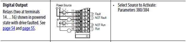
If there are wires on these terminals, you have a digital signal that is being used for status by another device, i.e. PLC or DCS. These statuses usually are interlocked to the I/O on a PLC and make it difficult to start unless programmed correctly. The illustration above shows the state of faulted.
Let’s compare to an expansion card example to stay consistent with the section of the blog at this point. These relays reside in Port 4. Let’s compare wiring in the example below:
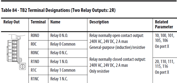
Program the drive relay function on parameter 10 for Ro0 and 20 for Ro1.
IMPORTANT: Drive “running” in PowerFlex 700 now is drive “active” in PowerFlex 750 series.
If you gathered information on the PowerFlex 700 before the drive failed, you can see how much easier the transition is to the PowerFlex 750 series drive, and you can concentrate on just the programming of the PowerFlex 750 drive and not have to assume some parameters, because they are unknown at the wire location on the terminal block.
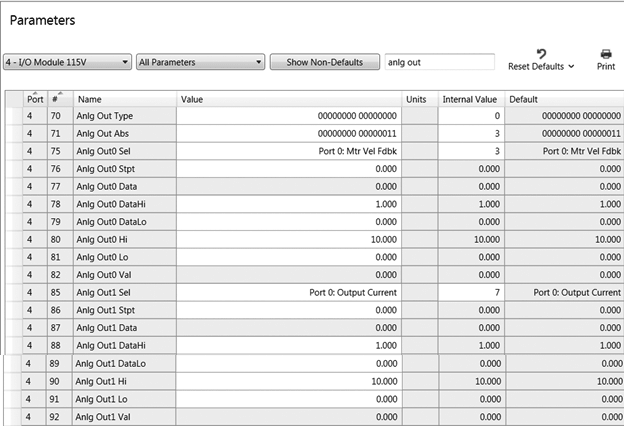
Now we will take the PowerFlex 700 drive example for the relay defaults and change the parameters in the PowerFlex 750 drive relays in port 4. The relay physically resides in port 4 so this must be the host and point back at a function in the drive port 0, such as “faulted” and “active” status so the relay changes state on the correct event.
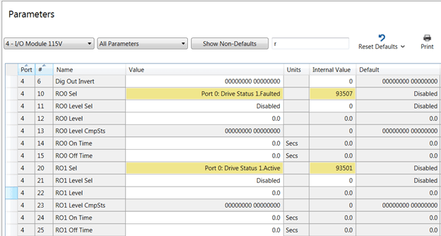
The upper left side of the capture above shows Ro0 is set to faulted and is selected, this relay should be wired normally closed (NC) if the relay needs to send a signal when the drive faults to other devices. The relay is pointed back to port 0 parameter 935 which has a string of bits with different functions we can choose the “faulted” status bit. Ro1 is selected to energize when the output is running or “active.”
The relay can also have delays for turning on or turning off Ro0 parameters (14, 15) or Ro1 (24, 25). Relays can also be used for levels to turn on and off also but will not be discussed in this literature. The relays can be also programmed for resistive and inductive loads on the relay output. Coils on the electromechanical relay on the drive would be considered inductive load for example. These relays are not intended to run small motors. Amp ratings are shown above.
Let’s take a few minutes and discuss the ethernet ports on both drives and some of the differences and advancements. The PowerFlex 700 drive is primarily a single port drive for most hard-wired applications. The digital and analog wires are landed on a predetermined location, and the drive is then programmed to perform when a signal is sent to that location. Digital inputs and relay outputs are “on off” signals, and analog signals are a continuous signal with magnitude; the larger the value, the more or less the drive will react (speed for example). It is always important to remember these concepts will be used over ethernet as well. For years, networking has been used to simplify installation and drastically cut the cost, as well. The serial communication market such as “blue hose” was prior to ethernet, but to this day the structure has not changed much, except now we can provide more information through ethernet with higher bandwidth on the networks.
Tag driven data in the PowerFlex 700 and PowerFlex 750 series drives, vs. the 1336Plus drives with bit and word structure allowed bits and word (16 bits) strings to be seen and understood from a data point of view. The advent of the ControlLogix processor allowed tags to be directly always accessed between the drive and the ControLogix controller.
PowerFlex 70 drive or PowerFlex 700 drive allowed an access to port 5. Port 5 used a 20-COMM-E (DPI port) communication adapter that has four mounting screws with a ribbon cable usually on the door of the drive. The status lights can be viewed through the cover of the drive.
It is important to know the IP address, subnet mask, and gateway information from the old PowerFlex 700 drive. If you have this information, skip this section.
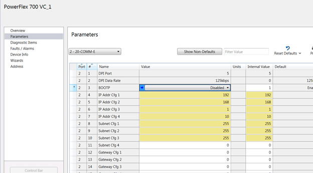
This is a Connected Components Workbench view on the PowerFlex 700 drive port 5 parameter list; observe these values. You may not have a gateway on your communications configuration. Gateways leave the building for remote access. Document the IP address and keep in mind parameter 3 is disabled for BOOTP.
You will place the addressing in the 20-750-ENETR in the PowerFlex 750 drive with this information. Port 6 has been left available because of cable access and addresses will be entered in port 6 of the PowerFlex 750 drive.
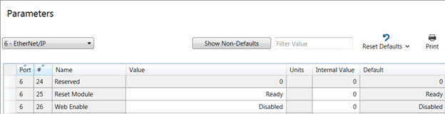
Here is a screenshot in port 6 of the PowerFlex 753 drive and the networking information that you will need to put in the different parameters.
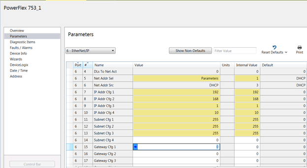
IMPORTANT: Parameter 5 in port 6 should be set to the “parameters” value to load the IP address into the drive from the HMI.
The default is dynamic host configuration protocol (DHCP), which means you would have to get an IP address from a router on the network. BOOTP would be used in case you wanted to assign the port address from the BOOTP server software included with your Logix software install. If you utilize the BOOTP server, you must disable the BOOTP prior to leaving the software window. If the adapter remains in BOOTP mode the next power cycle, it will wipe out the assigned IP address and drive will not communicate. Consider using BOOTP when installing MCCs, connect one device at a time on the network, assign an IP address to the device, then plug in the next device, etc., etc. This is much more efficient than the HMI assignment. DHCP assignment by far is the best approach, especially on large networks. The IP addresses constantly change though vs. fixed IP addresses with the other two methods mentioned above.
Once the drive has the IP address, cycle power to the adapter to finish the IP commissioning. Make sure you see the address in RSLinx® software or from the command prompt ping the IP address to make sure it is communicating. If you do not see the IP address, cycle power to the drive.
The PowerFlex 753 drive also has a web browser, and you can try to communicate that way also. You will need to enable the webpage shown below (parameter 26 port 6).
Please keep in mind, the above example is class C subnet masking. The network ID is the last octet and the network can hold up to 255 unique networking nodes. Other classes can be used, but it is strongly advised to consider network traffic when adding too many nodes on one subnet.
Let’s review the strategy one more time:
This article should give you a great head start on the procedure, and help you know what to look for inside and outside the drive prior to installing the drive. Please contact us with any additional questions you may have regarding programming the modernization from the PowerFlex 700 drive to the PowerFlex 750 drive.
The Rockwell Automation website contains literature of interest on the modernization of architect drives. The literature is updated constantly, and the literature library has a search for the following literature that begins with the following titles:
We hope you have found this blog useful in your modernization adventure. Please feel free to submit any questions to our staff regarding the material that may not have been part of the scope. We are here is assist you in any way possible.