
Blog > Automation > Drive Modernization Part III: 1305 to PowerFlex 525
Drive Modernization Part III: 1305 to PowerFlex 525
7/16/19 | Scott Savage, Rexel Technical Consultant
Blog > Automation > Drive Modernization Part III: 1305 to PowerFlex 525
7/16/19 | Scott Savage, Rexel Technical Consultant
This post is the third in a series of drive migration blogs, helping you find the right drive to replace one that has served you well. This installment will guide you through converting a 1305 to PowerFlex 525 drive. Other titles in this series include:
Welcome to those reading my blogs for the first time, and for those who have been following the series, thank you for reading these detailed blogs! Hopefully, you can modernize your drive to the latest model before you experience legacy drive failure, putting your facility at risk. Let’s explore the path to take with an existing 1305 and upgrade to one of our general-purpose drives, the PowerFlex® 525 drive.
The 1305 drive only required contact closures to the digital inputs to the drive. The PowerFlex 525 drive digital inputs operate on contact closures also, so this is a perfect drive to use for your upgrade. The 1305 is a V/Hz drive with simple motor control compared to today’s standards. The PowerFlex 525 drive can be programmed for V/Hz, and if the 1305 handled the load and broke it free, then the V/Hz mode with the PowerFlex 525 drive will also work. Don’t forget with any Allen-Bradley® drive, when you change the motor torque performance parameter to V/Hz, motor tuning is not needed. Just put in the FLA of the motor and start the drive.
Before we delve into converting your 1305 to PowerFlex 525 drive, let’s review two-wire vs. three-wire control.

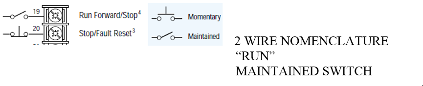
Quickly, let’s review two-wire control concepts. Allen-Bradley traditionally uses the term “Run” for a two-wire control term. “Run Forward” and “Run Reverse” are used for two-wire bi-polar control.
© Rockwell Automation®
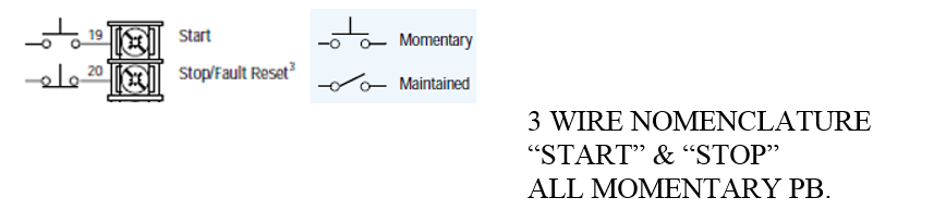
A three-wire control uses a momentary switch versus the two-wire control. Some applications and environments require three-wire control. Either method works, so it becomes a matter of preference as to which control method you choose to standardize.
© Rockwell Automation
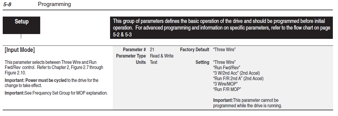
Now when you look at the 1305 drive parameter, you will understand the type of control that you have.
© Rockwell Automation
Download the parameters with either DriveExplorer™ (.csf) or DriveTools™ (.dno) and please observe Parameter 21.
Document the control wiring on the 1305 to prepare for the proper landing on the PowerFlex 525 drive terminals. Please keep in mind Parameter 21 will determine the control strategy for the field wiring and its location on the PowerFlex 525 drive. It is imperative to land the wires properly on the PowerFlex 525 drive and use the same control method as the 1305.
Here are some manuals to refer to for all this information:
© Rockwell Automation
The 1305 drive switches from the “Common” terminal to the input terminal, which performs a certain function, i.e., “Jog” or “Start”. The “Start” input becomes active or true when the switch (maintained for 2-wire control) is closed. The drive stops when the Start switch is open. The “maintained input” symbol in the figure below represents the switching device used for 2-wire control and is maintained. Notice all switching devices are maintained and not spring loaded.
© Rockwell Automation
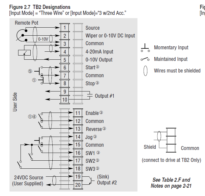
The 1305 drive switches all the digital inputs from the “Common” to the input terminal. For example, the “Start” input becomes active or true when the switch (momentary for 3-wire control) is closed momentarily. The start circuit seals and continues to operate. The drive stops when the Stop switch is opened. The “momentary input” symbol the figure above represents the switching device used for 3-wire control please observe terminals 6, 7, 8 (momentary). Notice some switching devices are momentary and some are maintained, always take note of the symbol in the user’s manual when wiring the devices to the PowerFlex 525 drive's terminal block.
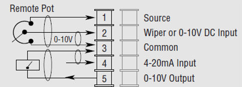
Please note the positions of the analog input and analog output locations on the 1305 terminal blocks. The positions determine whether you are using 0-10VDC signals or 4-20mA signals. The remote potentiometer terminal landings are always 0-10VDC and use 10K potentiometer. All Allen-Bradley drives use 10K potentiometers as a standard.
© Rockwell Automation
Hint: If using a 5K potentiometer on other drives and converting to Allen-Bradley drives, just double the maximum frequency to achieve the full range of 0-60Hz.
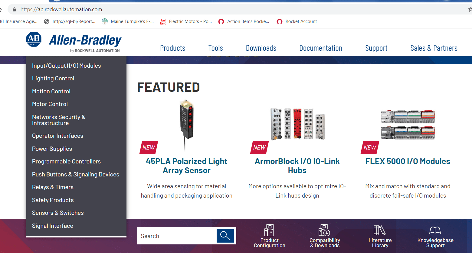
So now we know how to unwire and document the wire positions of the 1305 drive, make sure you mark the wires if they are not already labeled, and open the Powerflex 525 drive user manual. If you don’t have paper copies (which you can get from your distributor) or a downloaded electronic copy, you can go to the Rockwell Automation website and download from the Literature Library on the Rockwell Automation website:
© Rockwell Automation
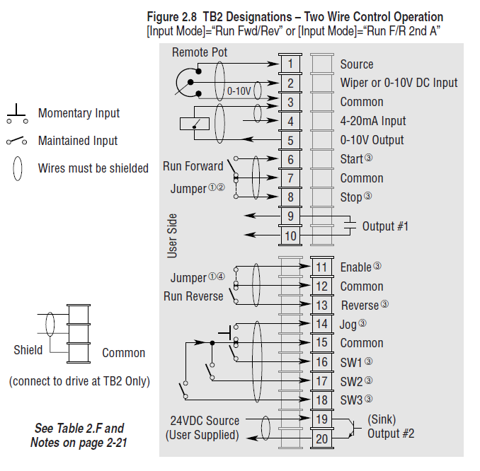
Pin 11 on the PowerFlex 525 drive is now the “Common” terminal on the 1305 drive. All other nomenclature is similar except one item: “2-wire Start” in the 1305 user manual is called “Run” (2-wire terminology in all other drive manuals) in the PowerFlex 525 drive user manual. “Start” is the term for 3-wire control in all other Allen-Bradley drive manuals.
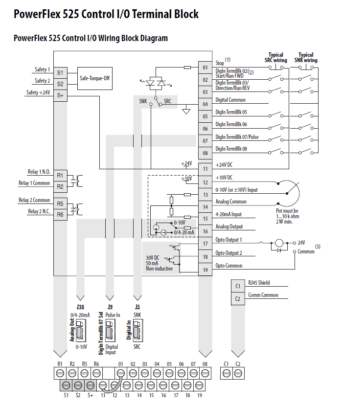
Let’s talk about bipolar control where the drive runs forward with one input and reverse for another output. Please look at the PowerFlex 525 drive terminals in the above illustration. Terminal two is “run forward” and terminal three is “run reverse”. Please note, “run” means 2-wire control and requires a maintained switch. Another important note, the yellow jumper remains in the circuit on the terminal block between terminal one and terminal 11.
With 2-wire unipolar applications vs. bipolar operation, the yellow jumper between terminal 1 and 11 remains in from the factory. Terminal 3 on the PowerFlex 525 drive needs to be disabled because you are running in one direction and only need terminal 2 for the “run forward” condition. Bipolar applications (forward and reverse) require both terminal two and three (already programmed).
With 3-wire control, you must remove the yellow jumper between terminal one and terminal 11. A normally closed stop pushbutton must be added to terminal one and a momentary normally open start pushbutton must be added to terminal two. Please note that terminal three “run reverse” should be programmed for “disabled.”
© Rockwell Automation
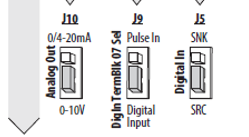
On the PowerFlex 525 drive J10 the analog out is set to 0-10VDC. If you need 4-20mA, then move the jumper up. J9 is set for a digital input, if you need a pulse input move the jumper up. J5 is the control mode of the digital inputs; it comes from the factory to be sourcing inputs (positive 24VDC from terminal 11). If you wish to use sinking (negative switching to DC common) inputs to the DC common, move the jumper up. Please keep in mind a ground fault on an input circuit will turn the input on when using sinking mode.
Analog inputs are traditionally used for speed reference. Because 1305 drives were used in simple applications, let’s look at two ways to use these analog signals below.
© Rockwell Automation
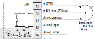
The first is speed reference, using a remote speed potentiometer, terminal 12 provides +10VDC to the circuit, and the wiper is on terminal 13. The wiper will move and gain resistance between the 12 and 13, which will change the voltage on terminal 13. The greater the voltage gets to terminal 13, the faster the speed is on the drive output. Please keep in mind, the pot must be 2 Watts minimum to operate long term. If you have a 10VDC or +/-10VDC signal for bipolar operation terminal, 13 would be the +10V or -10V and 14 would be common (0V). A 4-20mA circuit would have the 200 ohm resistor shown in drive circuit and + would be terminal 15, analog common would be terminal 14.
Analog outputs are usually used for speed feedback from the AC motor counter EMF. The greater the motor counter EMF, the faster the motor speed, and the greater the magnitude of the analog signal from the drive to another device. The analog output can be programmed for a variety of functions. Please check the PowerFlex 525 drive user manual for more options. The positive side of the signal either 0-10VDC or 4-20mA is terminal 16, the negative side is analog common or terminal 14. The factory setting is 0-10VDC to change to 4-20mA move jumper 10 shown above.
Most of us will wait until drive failure, praying the HIM (keypad) holds the program. Sometimes the keypad will not download from the old drive when it is plugged into the new drive (even if it is the same model). The 1305 has been obsolete for many years, so the odds of finding a good used drive are very slim. Please keep in mind, the shelf capacitor life for a new drive is six years, after that, the capacitors need to be recharged with a DC supply in voltage stepped up in slow steps to avoid catastrophic failure. So be careful with older drives that have sat in storage for a long time. The PowerFlex 525 drive is the most obvious path forward for the legacy 1305, with similar I/O structure and familiar features in the parameters of the firmware.
The most comprehensive way of capturing the parameters is to upload the program out of the 1305 drive with either DriveExecutive™ (.dno) (a part of DriveTools) or DriveExplorer software (.csf). Observe the present parameter settings in the 1305 and compare them on the list with the default setting from the factory. If the parameter setting is different than its default, it must be programmed in the PowerFlex 525 drive the same way.
In the example below, we will use a DriveExecutive example of a modernization project on a 1305 drive that was done recently and a Connected Components Workbench (CCW) (.ccwsln) parameter file that was created for the PowerFlex 525 drive from the uploaded DriveExecutive file.
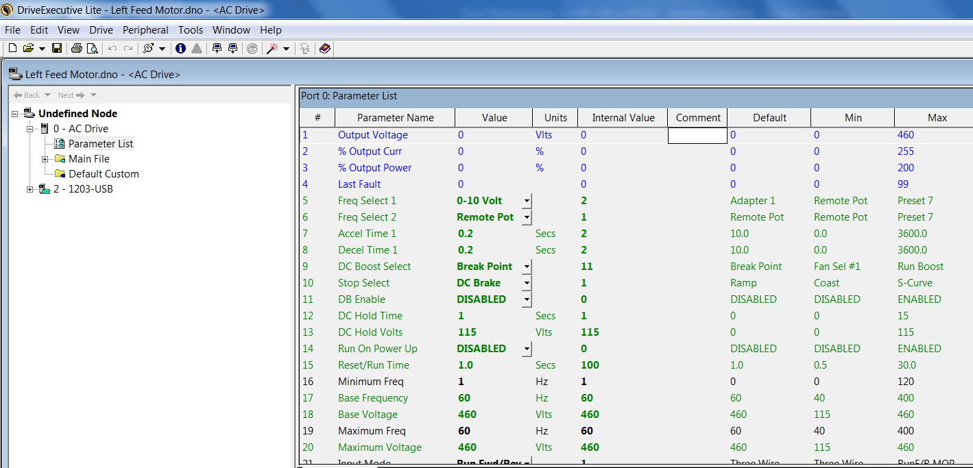
Compare the “Value” column to the “Default” column. For example, “Freq Select 1” is at a parameter setting of “0-10VDC.” The default parameter setting for “Freq Select 1” was “Adapter 1” (keypad). Check “Speed Reference 1” in the PowerFlex 525 drive to make sure it is set to “0-10VDC.” We will show the CCW software example to change that parameter. Any parameters in green in DriveExecutive are parameters of interest. Take 30 minutes and review the parameters that need to be changed.
Hint: This cannot be done after the drive has failed and has no power on the DC Bus to access the parameter files. Plan ahead.
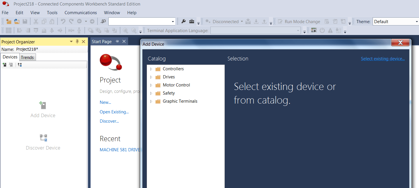
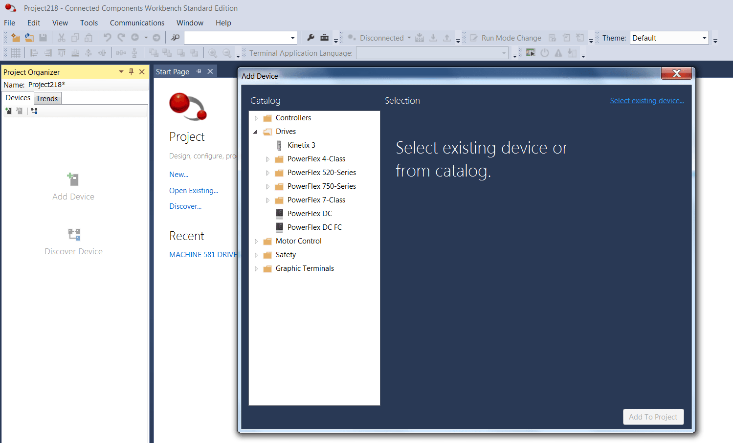
Start a new workup in CCW, choose the right drive from the Device Toolbox, open the parameters, and click on the one you need and edit them.
Start a new file:
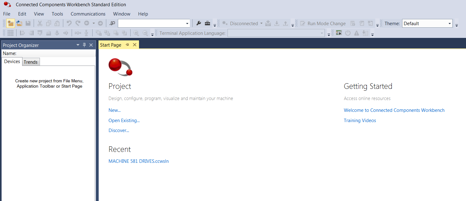
Click “New.”
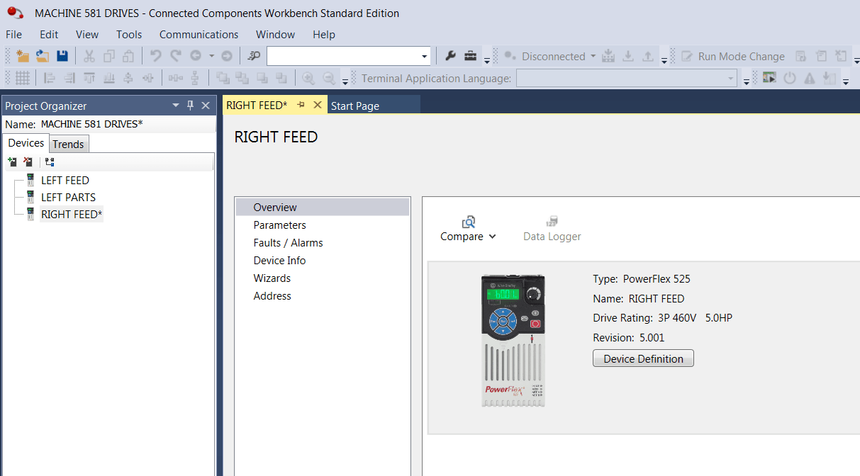
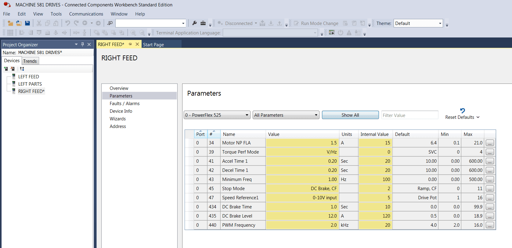
This is an example of the CCW workup, the “Right Feed” parameter set has been selected, and now we can review the parameters for this drive and observe the changes we made to the CCW file. This is a good example of multiple drives on a machine shown in the “Project Organizer” on the left. The drive highlighted is on the right in the workspace that shows the drive areas to access.
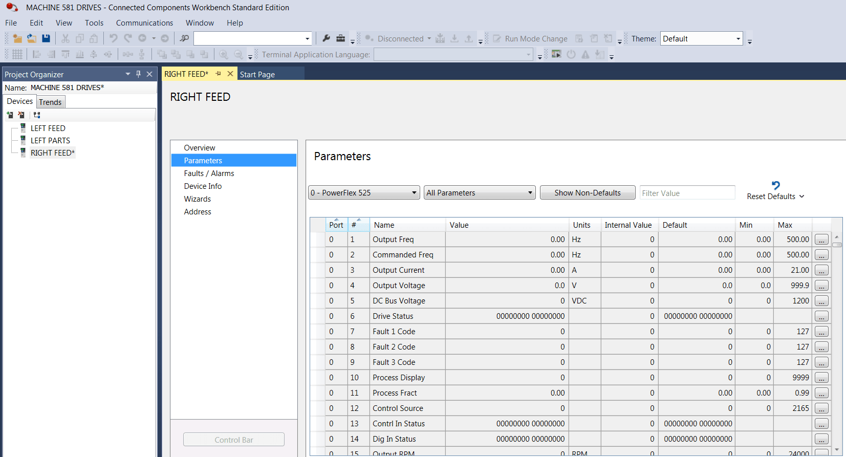
Now you are observing the parameters in the drive. To see what has changed from default settings, click on the “Show Non Defaults” pushbutton shown below.
The “Non Defaults” (parameters that have changed) are shown after the parameters were changed in CCW for the PowerFlex 525 drive. This is a good way to check your work.
Now let’s see how the filter works on the CCW software. To save time, you can type the name of the parameter into the filter, each letter you apply narrows the parameters down for your selection. You can even filter by parameter number if you know it.
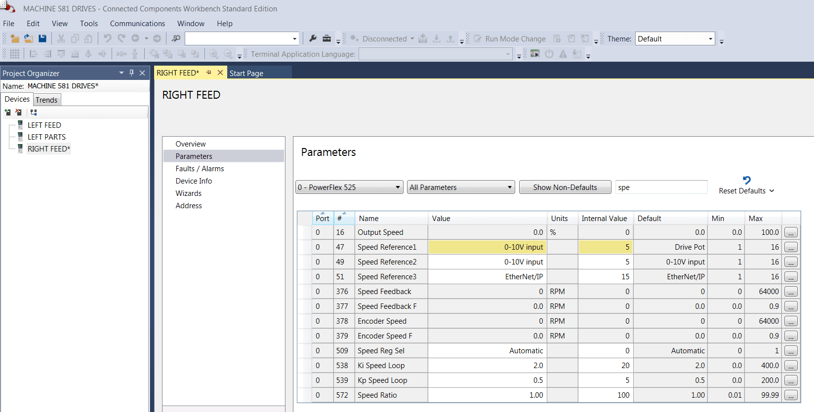
The screenshot above shows “Speed Reference 1,” which is the equivalent of the 1305 “Freq Select 1” parameter. If you click on the box in the “Value” column, you can select from a list of choices in the firmware of the drive. If it is a numeric value such as the “Acceleration” parameter, click and change the value. When you hit the “Enter” key, the parameter will be permanently changed until the next edit of the parameter.
Please keep in mind some parameters can’t be edited while the drive is running, including:
The PowerFlex 525 drive “Start” command can only function from one location.
“Parameter 46” is the “Start” parameter setting for the drive. It can be used in one the following locations:
Keypad (integral to drive) – Factory default to start the drive is from the embedded HIM on the front of your PowerFlex 525 drive. This is convenient to test the drive without a motor attached and test the drive upon powerup of the unit.
Terminal Block (embedded on drive) – Used when controls are hardwired to the drive, so start signal is directly coming from a pushbutton or maintained selector switch.
DSI/Serial Port (RJ45 Jack) – Commonly used for the HIM mounted on an enclosure door; the cable provided with the remote HIM plugs into the DSI port on front of drive.
Network (DSI serial communications and Modbus RTU protocol) – DSI / serial port can also be used for Modbus communications and can daisy chain five drives together to a Modbus controller.
Ethernet/IP – Place the drive on an Ethernet/IP control network with our CompactLogix™ or ControlLogix® controllers and connect the drive to the PLC in 15 minutes or less using Premier Integration by Rockwell Automation.
The 1305 drive was very simple compared to today’s advancements with AC drives. It only ran in one mode: the simplest form of torque control called Volts/hertz mode. The PowerFlex 525 drive can run in a V/Hz, and the performance will be the same as the 1305. The default setting on the PowerFlex 525 drive performance torque mode (parameter 39) is set for Sensorless Vector mode. If you want the same performance, just put the drive in V/hz and program the Motor Full Load Amps to motor nameplate value. The PowerFlex 525 drive also has an additional setting called Motor OL Current (parameter 35). Depending on preference, it should be slightly higher than the Motor Full Load Amps (10% is good); just verify the motor has a 1.15 service factor.
Any other torque performance mode settings (parameter 39) such as Sensorless Vector or Flux Vector require the drive and motor to go through an AutoTune (parameter 40), so for the 1305 replacement, we don’t recommend Sensorless Vector Mode or Flux Vector (Velocity). If you do run in Sensorless Vector the AutoTune is required, and all the motor data must be entered prior to the AutoTune. The Autotune requires this information or the Autotune will fail. The drive’s response in Sensorless Vector Torque Mode will also be faster and may affect your process so be careful. Please remember once you AutoTune the drive, if you change the motor, you will have to re-tune the drive and save the parameter set of the new motor data. Two areas of interest in the motor tune parameters are the resistance in the windings (Voltage IRDrop par#496) and the leakage current from the windings (Flux Current Reference par# 497) to the iron of the motor. All motors are slightly different, hence the reason for the re-tune. V/Hz does not require initial tuning, nor do you have to re-tune on a motor change out.
Thank you for reading my blog. Be prepared for the moment at hand. If you have any questions along the way, we’re here to help. Contact us today!