
Blog > Automation > VFD Series Part 5: How Do I Choose an Electric Motor?
VFD Series Part 5: How Do I Choose an Electric Motor?
4/27/18 | Kevin Beach, Rexel Technical Consultant
Blog > Automation > VFD Series Part 5: How Do I Choose an Electric Motor?
4/27/18 | Kevin Beach, Rexel Technical Consultant
I’d like to start this blog by thanking everyone who has clicked, read, shared, and commented on the VFD blogs that have been posted to date. When you’re spending the time to write, rewrite, edit, rewrite these over and over so many times, it truly helps make the effort worth it knowing those of you out there are getting something out of these. So, my heartfelt thanks for making it all worthwhile. – Kevin Beach

AC electric motors are the engine of manufacturing and keep the economy running. They have been driving industry since shortly after Nikola Tesla patented the AC induction motor in 1888. If you’ve ever looked at an industrial motor catalog, you know finding the right motor in an industrial motor catalog can be a daunting task. With a huge selection of motors in the same voltage, HP, and mounting, which one do you choose? We can make it a bit simpler but first, let’s take a quick walk down technical lane and go through how an electric motor works.
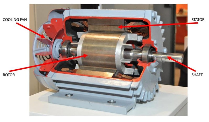
In the cutaway above we can see the internal components of a three-phase electric motor. The stator is mounted in the housing and is therefore stationary and the fan and rotor are mounted to the shaft and will rotate. The stator consists of a bunch of overlapping windings that are offset by 120° electrically. When power is applied to it a magnetic field is created that rotates at what is called synchronous speed.
At the same time, windings in the rotor are closed and electromagnetic force or emf is generated in the opposite direction from the stator creating torque and causing rotation of the shaft. The rotor will never quite reach the speed of the stator and that difference in speed is called motor slip. Therefore, under load, an 1800 RPM base speed motor will actually operate around 1740-1770 RPM at 60 HZ.
This is a totally simplified explanation but should serve our purpose for this blog.
Now back to that mind-numbing motor catalog. As with anything else in an industrial environment we always start with the application. And with any application, we must look at the work being done, the environment, the power needed, and the voltage being used. Let’s start with an easy one, the motor will be located in a climate-controlled, clean, industrial environment like an electronic parts manufacturing plant, belted to the drive pulley of a conveyor and 480 VAC is plant power.
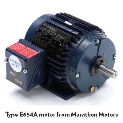
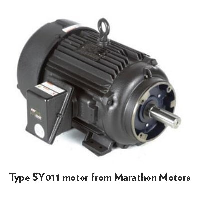
If it just uses a contactor to start it then we can use any motor with the correct HP, mounting, and voltage. This blog is not intended to help with motor sizing but rather the correct type of motor for an application. So, if we were given a need for 2 HP and 1800 RPM base speed then we would pick a foot mounted motor since it is belted to the load. The specs would be 2 HP, 1800 RPM base speed, 145T frame, and 3 full load amps. As we talked about previously the 1800 RPM base speed will not be seen due to the slip inherently in the motor, so the actual speed will be more like 1750 RPM. Click on the picture for the complete data sheet on this motor. Yeah, yeah; I know there are some additional considerations when using a belt drive on a motor, like a roller bearing on the drive end, but that is beyond the scope of this blog.
The next day the application has been changed and the motor speed needs to be varied depending on the product being run at the time. So now we are not using a contactor but a variable frequency drive (VFD) instead. (See previous blogs for information on VFDs.) The additional information we need to gather is the operating speed range and we should really take a deeper dive into the application. The speed range can vary greatly across electric motors but the most important thing in the motor is the insulation class. When the motor will run at speeds less than base speed it is important to know how the motor cools itself. Totally enclosed fan cooled (TEFC) is the most common industrial motor housing and is fine for most applications. But when you’re running it at reduced speed it is critical to remember the fan is attached to the non-drive end of the motor shaft turning at motor speed and the fan’s airflow drops by the cube law. In other words, a 1750 RPM motor running at half speed, 875 RPM, is only moving 1/8 the volume of air over the cooling fins than at the base speed. This why insulation is like way important.
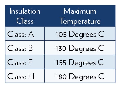
Most new industrial motors are insulation class F or H which is what we are looking for in a VFD controlled motor. The insulation classes are based upon the maximum temperature in the windings of the motor.
These are all based upon NEMA MG1 Guidelines established for adjustable speed motor applications. These guidelines apply to motor torque, speed, noise, and other factors but this blog is only considering motor insulation. As we already discussed, the airflow drops drastically with speed so generally, the higher the insulation class or winding temperature the wider a speed range the motor will be able to accommodate. There are, of course, always exceptions to this.
In our sample application, the conveyor needs to be able to run from full speed down to 10% of max speed. For our purpose, we’ll assume max speed is motor base speed.
So, going back to selecting the motor, most industrial motors today are what is generally referred to as Inverter Duty which means they can be used with a VFD, but it may not give the speed range needed. The speed range can range anywhere from 2000:1 down to 2:1. Our conveyor application requires 1800 to 180 RPM or 10:1. The motor we had already selected has a constant torque speed range of 1000:1 which is more than ample for our needs, so the motor does not to be changed. If it had been 2:1 a different motor would be needed. To be safe if this motor had been rated for 10:1 we may still want to change motors.
Our application is a moving target and now due to space constraints, it’s been decided they need to use a right-angle worm gearbox between the motor and drive belt. Because they said they want to mount the motor directly to the gearbox then we need to add some way to mount the motor. We need a mounting flange on the drive end of the motor. The most common standard flanges are referred to as C-Face and are a NEMA standard across all motors and gearboxes. Looking at our motor catalog we see the standard flange for 2 HP is 145TC. The smaller NEMA frame sizes usually come with both the mounting base and the C-Flange. This flange will bolt directly to a worm gearbox with the correct 145TC adaptor on the input.
This is a pretty basic primer on selecting a “normal” industrial motor in a “normal” environment but in my day-to-day world I run into mostly more specialized motor needs so let’s take a quick look at some of those.
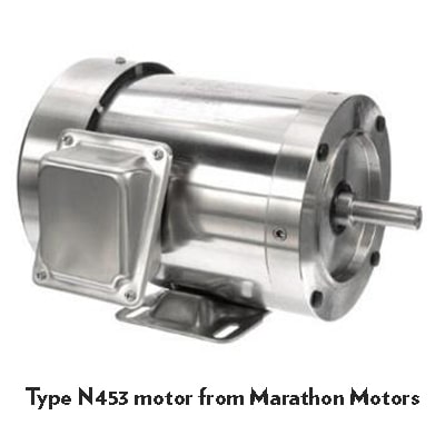
The Food and Beverage and Pharma industries have cleanliness issues which are dictated by FDA regulations. Their equipment cleaning requirements range from cleaning solvent wipe down to high-pressure washdown. And the motor manufacturers do have both epoxy-painted motors and complete stainless-steel housings to accommodate them. When cost is an issue, epoxy paint is generally a less expensive option.
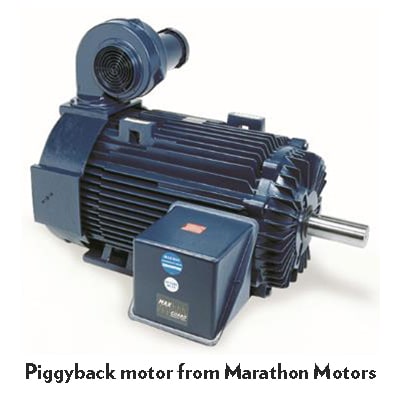
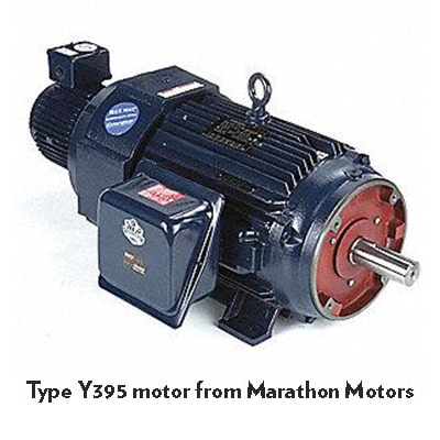
Paper and steel mills are rather hot and nasty places. Red hot temperatures in the case of steel and steam and water in paper create a need for some type of extra cooling for the motors. The most common way to accomplish this is with a blower cooled motor (TEBC) and these blowers come in a couple of mounting styles; axial or piggyback. Axial means the blower is mounted on the non-drive end of the motor and will add additional length to the motor which will need to be considered during selection.
The piggyback blower adds very little to the overall length, but it is substantially taller than a standard motor which, again, needs to be considered.
For both, piggyback and axial blower cooled motors a starter is needed for the blower motors.

The aggregate industry has a set of really different issues that need to be addressed. Since they are used on some pretty shock-filled applications like crushers and pulverizers they use 100% cast iron construction, high strength steel for the shafts, extra high starting torque, roller bearings on the drive end, special seals, epoxy paint, even rodent screens. They are designed for use outdoors in the harshest environments including heat, rain, cold, snow, you name it. And here in the north country where I live and work, they have to sit idle outside buried in snow all winter and start right up in the spring. They are technically referred to as aggregate duty but also “crusher” duty.
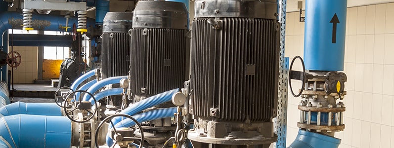
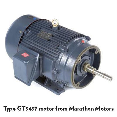
Pump motors are another specific motor that can bite you on the butt if you don’t know them. When mounted on the pump they appear to be a standard NEMA flange motor but, like an iceberg, what’s below the surface is what sinks you.
These pumps often have special mounting flanges and pump specific shafts. These shafts are generally longer so they can reach down into the pump and often have features machined in so the pump impeller can be mounted directly on the shaft. Most motor manufacturers have a large selection of motors they have developed in conjunction with the pump manufacturers and meet pump specific standards. They are often designated as J Frame and would show as 56J rather than 56C or whatever the frame number is followed by a J.
An increasingly common motor today is the permanent magnet AC motor. The PM DC motor has been around for decades, but the AC version is a relative newcomer. As its name implies, there are permanent magnets located in the housing of the motor but unlike AC induction motors, no energy is induced to the rotor. As a result, they are more efficient (2-4%), have no-slip and are considered synchronous motors, run cooler, and have higher power factors. Since they use rare-earth magnets, they are up to 2X as powerful as standard permanent magnets allowing for smaller and lighter motors versus AC induction. It is important to note line starting is not an option and a VFD must be used with PMAC motors. PMAC motors are being used extensively in energy savings projects today.
Most motor companies have an extensive amount of technical information available to help you in the final selection process. Just click on the motor images and then click on the catalog number to see the technical data for each of them. Once there you can scroll down and get the performance curves and the drawings.
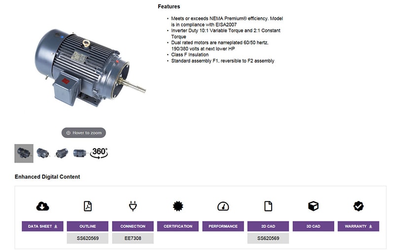
Pictured: Screenshot of a Marathon Motors web page; note the purple buttons for the datasheet, outline, 2D CAD, and 3D CAD.
Beyond what we have discussed here, there are lots of other specialty motors such as farm duty/agricultural, HVAC, fan motors, car wash motors and many more but this blog is dedicated to industrial motor selection. For questions or more information, contact us today!
This is part five of our popular, on-going variable frequency drives (VFD) series. Don’t miss the rest of the series: