
Blog > Automation > VFD Series Part 4: Good Panel Design
VFD Series Part 4: Good Panel Design
3/10/17 | Kevin Beach, Rexel Technical Consultant
Blog > Automation > VFD Series Part 4: Good Panel Design
3/10/17 | Kevin Beach, Rexel Technical Consultant
Good Panel Design is Everything – Or, How to Not be Your Own Worst Enemy
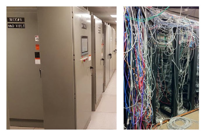
What you wanted… What you got.
If I had a dollar for every time I was shown a complete mess of an electrical panel, I’d have…well, a whole lot of dollars for sure. One time while at an end-user site with a Rockwell Automation® Field Service Engineer I heard a comment about panels that I think is well worth repeating here.
This particular end-user was asking why he was getting communication failures on his PowerFlex® VFDs. At one point, he took us out and showed us, what he called, a gorgeous panel. And it was, there were around 60 low HP drives in it as well as a lot of process type controls and an Allen-Bradley® ControlLogix® system. When the end-user technician finished talking about the gorgeous panel, the Field Service Engineer said, “I’ve seen lots of good-looking panels that simply weren’t designed right” which has certainly stuck with me ever since. In this particular case, there was not sufficient space above and below the drives to allow for adequate airflow over the heatsink on the back of the drives which resulted in a communication failure as the communication processor was sitting right on the heatsink. Oops!! They kept getting heat-related failures and, even worse, they were usually at 2:00 in the morning. We want to help you avoid that. So, let’s talk about designing a drive panel for success.
5 Questions and Considerations for Successful Drive Panel Design
First, consider the environment the panel is going to be mounted within. For good panel design, ideally, it should be in a dedicated motor control room which would allow for a controlled environment and eliminating the issues of potentially corrosive or other harmful gasses. It also could prevent unauthorized entry into what is an electrically dangerous environment; we’ve all seen those arc flash videos.

Environmental challenges can increase the risk of arc flash incidents in electrical panels
But if that’s not possible and the drive is going to be out on the plant floor, be aware of any potentially corrosive gases or vapors that could be present and the temperature and humidity at that location. For good panel design, select an enclosure rating that will protect all the devices inside it from corrosive gases or vapors and cool it accordingly. You will need to know all the heat-producing devices before you can talk about cooling. Your Account Manager can help you make the proper selection of a Hoffman enclosure.
We have discussed much of this in previous installments:

Now from a drives perspective, as the heatsink fins align along the long axis of the drive, it is essential to have sufficient clearance above and below each drive to allow the fan to push adequate air across those fins. Most of today’s drives are “bookshelf” design so that they can be mounted against each other like books in a shelf allowing for potentially using a smaller enclosure but the spacing above and below MUST meet the manufacturer’s specifications. And when they say clearance, they do mean clearance. That Panduit wireway you put between the drives does NOT count as clearance.
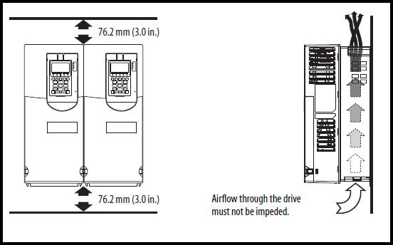
The above is taken from the Installation Manual for Rockwell Automation PowerFlex® 750 Class VFDs.
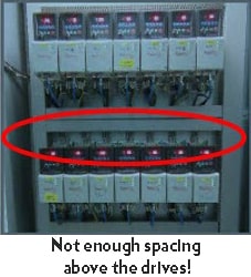
Note, the minimum clearance above AND below the drive is 3 inches while the drives are touching each other on the sides, the aforementioned bookshelf design. The wire way would need to be more than 3 inches away from the bottom or top of the drive. Oh, and any other drives mounted near these would ALSO need to be 3 inches above and below the drive. So, the spacing above these drives to the next drives above them would need to be 6 inches PLUS the width of the wire way. Anything less than that will absolutely present a problem for you or your customer down the road as the airflow will be restricted.
Another way to help reduce heat-related issues within a drive panel is to use “flange mounted” drives. These are designed to have the heat sinks fins outside the enclosure putting the major heat source away from your electronics.
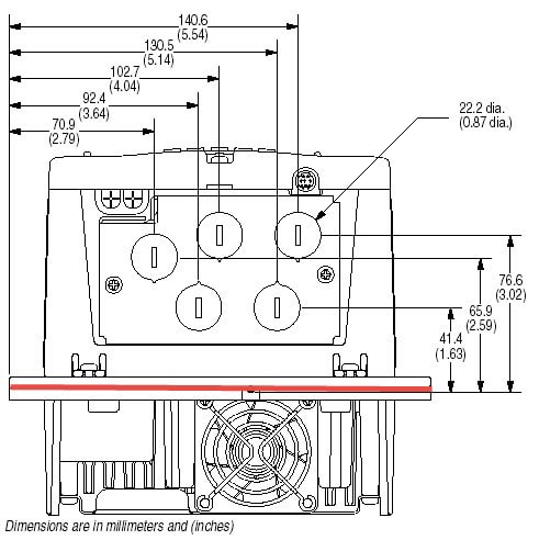
Looking up at the bottom of a flange mount PowerFlex® 70, the red line shows the back of the cabinet.
Proper grounding and bonding are essential in today’s industrial environment. Gone are the days where we could hire someone off the farm and count on them to have the ability to keep your plant running what with all the computers, precision instrumentation, data collection, and internet requirements in today’s manufacturing environment.
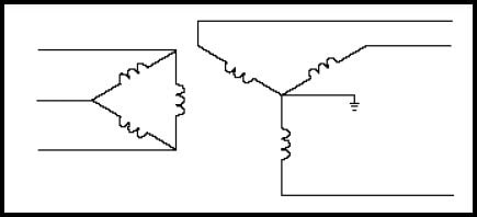
Grounding is simply connecting all the “current carrying” elements of your system to earth such as the neutral of a power transformer. There are several different ways to ground your system, but the “best practice” is Delta / Wye with grounded wye neutral.
The benefits of doing this are increased safety, providing a direct path for common mode current, controlled common mode noise current, and others.
Bonding is connecting all the conductive elements that normally aren’t supposed to be carrying current to put them all at the same potential, creating a low impedance path back to the source. But the system still needs to be grounded.
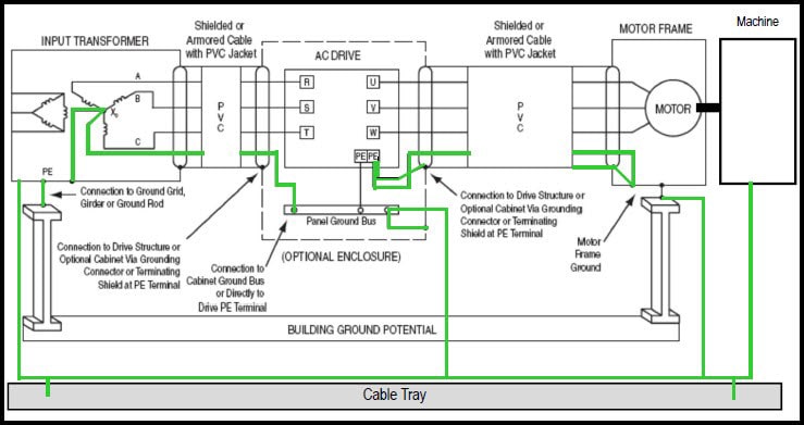
A properly grounded and bonded system is safe and helps control common mode noise.
A final piece of advice on grounding, skip those gorgeous painted back panels and go for galvanized to improve the grounding. If you have to use painted, then be certain to scrape off the paint at connection points. Function over form.
Click Here to Download our FREE Control Panel & Enclosure Guide

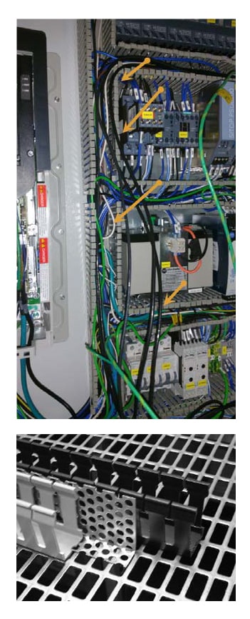
Another consideration is the wireway you use in the panel and how you route the different voltages through your cabinet. The picture to the right shows power, signal wire, unshielded Ethernet and 24VDC all mixed together. This is a sure-fire way to get that 2:00 AM call. Always try to keep the most space possible between your various cables and wires within your enclosure. Even something as simple as a shield between your wireways can help you sleep better at night.
For more information, you should check out Rockwell Automation’s Industry Installation Guidelines for Drives for more complete and industry-specific installation information (PDF file download).
Following the best practices we have outlined and asking yourself the right questions will help improve your drive panel design. Consider the environment. Double check; are you following documented clearance guidelines? Are you following proper grounding and bonding guidelines? For questions or more information, contact us today!
This is part four of our popular, on-going variable frequency drives (VFD) series. Don’t miss the rest of the series: