
Blog > Automation > VFD Series Part 7: How to Connect the Shield in VFD Cable
VFD Series Part 7: How to Connect the Shield in VFD Cable
8/20/19 | Kevin Beach, Rexel Technical Consultant
Blog > Automation > VFD Series Part 7: How to Connect the Shield in VFD Cable
8/20/19 | Kevin Beach, Rexel Technical Consultant
How to Connect the Shield in VFD Cable
We’ve had several blogs posted on VFD cables, panel design best practices, and noise mitigation, and we hope we helped reduce some of the gotchas when dealing with VFD and the harmonic issues they create. A question we still field routinely is, “Do I need to bond both ends of my motor cable, or do I leave one loose?” Well, the simple answer is “DEPENDS”! Back in the day, one end would be left loose, but as VFDs have started using very high switching frequencies (See “What the Heck is a Variable Frequency Drive?”), the electrical noise created by the drive has become an ever-increasing issue in modern process systems. There are two separate but equally important components of this:

These both have decidedly similar but opposite functions. Motor cables need to keep radiated electrical noise from leaking into other components, and feedback cables need to keep that same noise from entering the cable and corrupting the signals. We’ll look at the motor (load) side first. Load or motor cables need to be able to contain the electrical noises created by the drive. These cables should meet the NFPA-79 Standard (See “Choosing VFD Cables Just Got Easier”), which calls for a braided shield to be under the jacket of the cable. When both ends of the shield are bonded to both the motor and the drive, that will keep the noise from leaking out. The field in the windings switching on and off at high frequencies (typically 2-8 kHz) it induces voltages that can affect any low voltage signals, such as encoder signals causing them to become erratic and inaccurate. By grounding the motor housing by way of the shield helps to isolate the induced noise back to the source
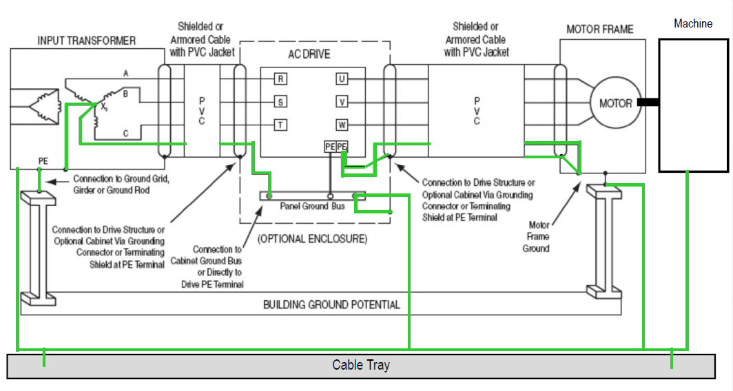
Possible fully grounded system using shielded cables on both the line and load side.
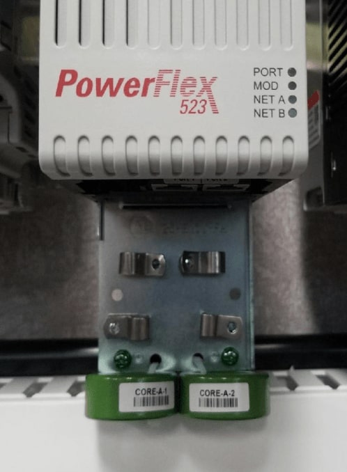
The picture to the right shows an optional EMC grounding plate. This gives a clean method to pass the cables through the EMC cores and land them on the drive. This plate is grounded to the drive and gives a continuous path for the electrical noise.
But why are there two, you ask? Well, the line (input) cable also should be shielded as it too is a conductor of noise. Don’t panic though, as that only has to go between the drive and line reactor. The standard power cable can go from there to the power source.
The cores are not necessary all the time and are used primarily in CE certified applications to reduce RF emissions. Not all drives will use ferrite cores for this, so consult your specialist for what devices are required to meet CE.
Not every application requires feedback cables or signal cables, but when they do, it is always best to route low voltage and high voltage separately. Of course, this is not always practical. So, in the case where they will be near each other, the bonding of the feedback cable is also of major importance. The reason, in layman's terms, is with a shielded signal cable, you want to capture noise that might be induced elsewhere in the system (i.e., motor cable) and keep the potential and current flow grounded in one direction to protect the clean signal inside the shield.
So, in a nutshell, power cable shields are bonded to both the motor and drive and the feedback to the drive only. If you need help connecting the shield to VFD cable, our Automation Specialists are here to help. Contact us today!
This is part seven of our popular, ongoing VFD series, and it will show you how to connect the shield in VFD cable. Don’t miss the rest of the series: